Installation
38
1SVC 440 795 M0100
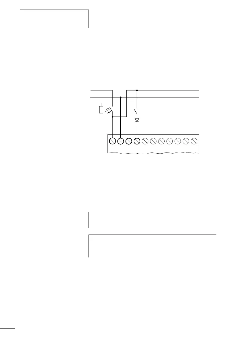
With longer cables you can, for example, connect a 1 A diode
(e.g. 1N4007) with a blocking voltage of at least 1000 V in
series with the CL input. Ensure that the diode is connected
in relation to the input as shown in the circuit diagram,
otherwise the logic relay will not detect the 1 signal.
Figure 14: AC input with suppression diode for CL-AC1 and
CL-AC2
CL-AC2:
Inputs I7 and I8 on the CL-AC2 have a high input current.
Neon bulbs with a maximum residual current of 2 mA/1 mA
at 230 V/115 V can be connected to I7 and I8.
Two-wire proximity switches have a residual current in the
“0” state. If this residual current is too high, the logic relay
input may only detect a “1” signal.
Use therefore the inputs I7, I8. An additional input circuit is
required if more inputs are needed.
L
N
LNN
I1
F1
h
Always use neon bulbs that are operated with a separate
N connection.
i
Caution!
Do not use reed relay contacts at I7, I8. These may burn or
melt due to the high inrush current of I7, I8.
 Loading...


