Connecting the inputs
37
1SVC 440 795 M0100
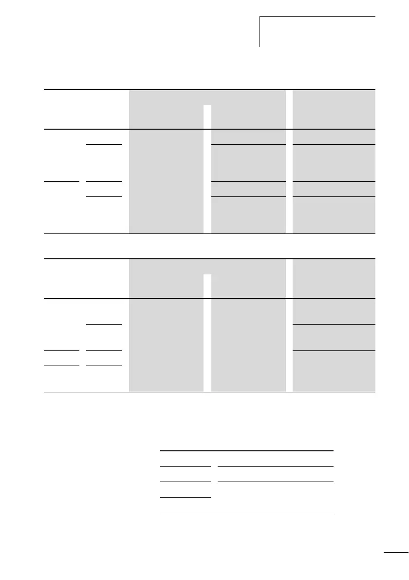
Table 1: Input signal values CL-AC1
Table 2: Input signal values CL-AC2
Cable lengths
Severe interference can cause a “1” signal on the inputs
without a proper signal being applied. Observe therefore the
following maximum cable lengths:
Voltage range of the input signals Input current
OFF signal ON signal
CL-LSR/
CL-LMR
I1 to I6 0 to 6 V AC 14 to 26.4 V AC 4 mA at 24 V AC
I7, I8 greater than 7 V AC
or greater than
9.5 V DC
2 mA with 24 V AC and
24 V DC
CL-LMR I9, I10
14 to 26.4 V AC 4 mA at 24 V AC
I7, I8 greater than 7 V AC
or greater than
9.5 V DC
2 mA with 24 V AC and
24 V DC
Voltage range of the input signals Input current
OFF signal ON signal
CL-LSR/
CL-LMR
I1 to I6 0 to 40 V 79 to 264 V 0.5 mA at 230 V AC/
0.25 mA at 115 V AC
I7, I8
6 mA at 230 V AC/4 mA
at 115 V
CL-LMR I1 to I6 0.5 mA at 230 V AC/
0.25 mA at 115 V AC
CL-LER/
CL-LET
R1 to
R12
I1 to I6 40 m without additional circuit
I7, I8 100 m without additional circuit
I1 to I6 40 m without additional circuit
R1 to R12
 Loading...


