Wiring with the logic relay
86
1SVC 440 795 M0100
Rules for wiring relay coils
To ensure a clear overview of all relay states only assign the
same coil function once to a relay (
ä, S, R). However,
retentive coil functions such as
ä, S, R can be used several
times if required by the circuit diagram logic.
Exception: When using jumps to structure a circuit diagram,
this coil function can also be used effectively several times.
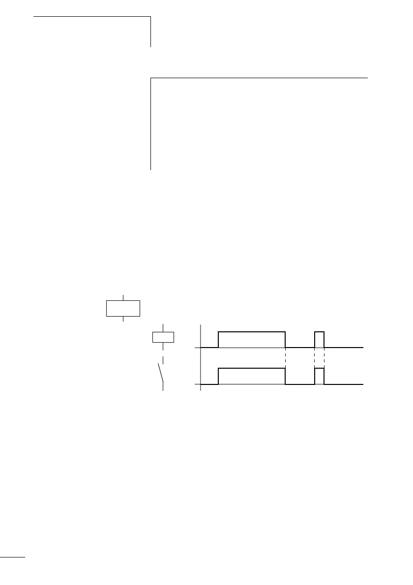
Relay with contactor function
Ä
The output signal follows immediately after the input signal
and the relay acts as a contactor.
Figure 39: Signal diagram of contactor function
Display in the logic relay:
• Output relays Q:
ÄQ1 to ÄQ8 (depending on type)
•Markers M, N:
ÄM1 to ÄM16, ÄN1 to ÄN16
• Function relays (Text) D: ÄD1 to ÄD16
• Output relays S: ÄS1 to ÄS8
•Jumps: Ä:1 to Ä:8
h
The coil functions Ä, Å, è, È, (contactor, contactor
negated, cycle pulse falling, rising edge) must only be used
once for each relay coil. The last coil in the circuit diagram
determines the status of the relay.
When controlling a contactor or relay, the control coil
is only present once. Create parallel circuits or use Set,
Reset as a coil function.
on
on
 Loading...


