Working with contacts and
relays
87
1SVC 440 795 M0100
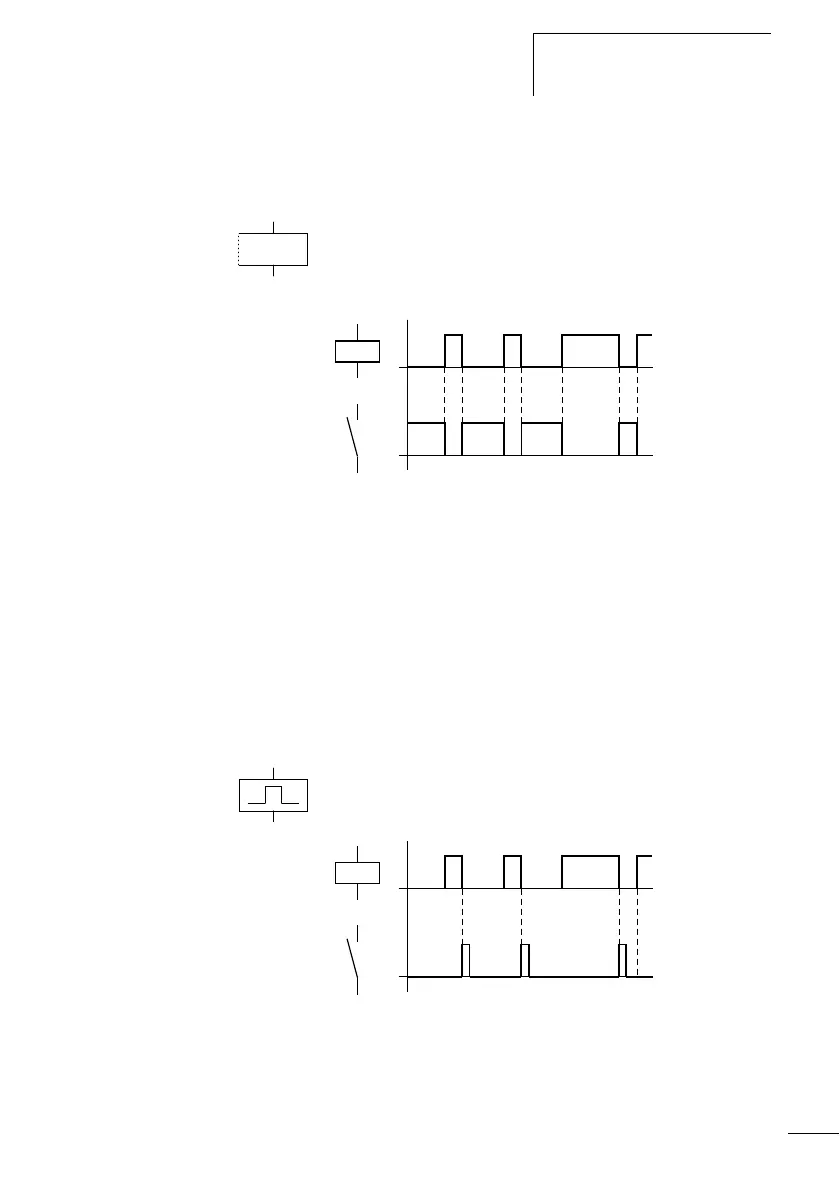
Contactor function with negated result
(inverse contactor function)
Å
The output signal is simply an inversion of the input signal;
the relay operates like a contactor with contacts that have
been negated. If the coil is triggered with the 1 state, the coil
switches its n/o contacts to the 0 state.
Figure 40: Signal diagram of inverse contactor function
Display in the logic relay:
• Output relays Q:
ÅQ1 to ÅQ8 (depending on type)
•Markers M, N:
ÅM1 to ÅM16, ÅN1 to ÅN16
• Function relays (Text) D: ÅD1 to ÅD16
• Output relays S:
ÅS1 to ÅS8
•Jumps:
Å:1 to Å:8
Falling edge evaluation (cycle pulse)
è
This function is used if the coil is only meant to switch on a
falling edge. With a change in the coil state from 1 to 0, the
coil switches its n/o contacts to the 1 state for one cycle.
Figure 41: Signal diagram of cycle pulse with falling edge
on
on
on
on
 Loading...


