Working with contacts and
relays
89
1SVC 440 795 M0100
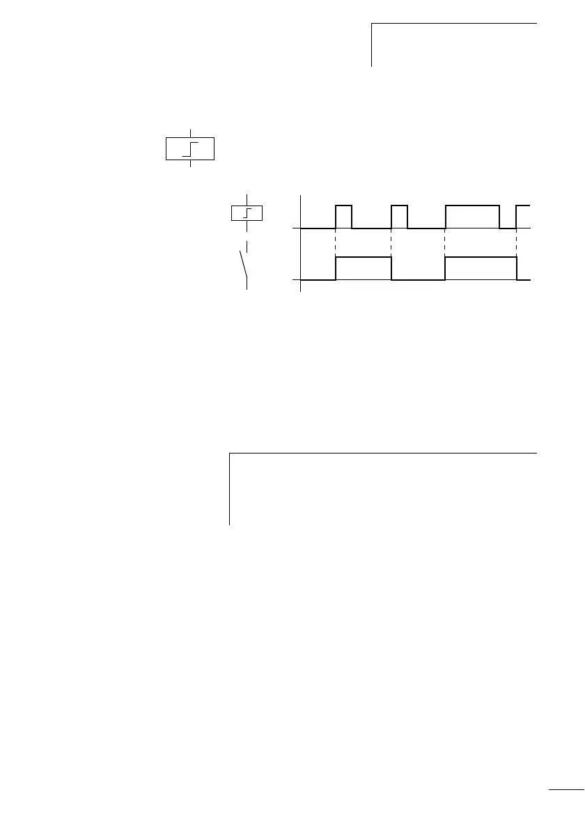
Impulse relay ä
The relay coil switches whenever the input signal changes
from 0 to 1. The relay behaves like an impulse relay.
Figure 43: Signal diagram of impulse relay
Display in the logic relay:
• Output relay Q:
äQ1to äQ8 (depending on type)
•Markers M:
äM1to äM16
• Function relays (Text) D: äD1to äD8
• Relays S: äS1 to äS8
on
on
h
A coil is automatically switched off if the power fails and
if STOP mode is active. Exception: Retentive coils retain
signal 1 (a section “Retention (non-volatile
data storage)”, Page 221).
 Loading...


