Wiring with the logic relay
90
1SVC 440 795 M0100
Latching relay
The “latch” and “unlatch” relay functions are used in pairs.
The relay picks up when latched and remains in this state
until it is reset by the “unlatch” function.
:
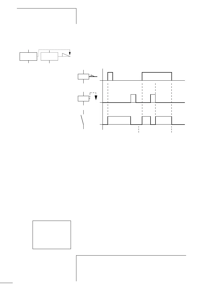
Figure 44: Latching relay signal diagram
• Range A: The set coil and the reset coil are triggered at different
times
• Range B: Reset coil is triggered at the same time as the set coil
• Range C: Power supply switched off
Display in the logic relay:
• Q output relays:
SQ1to SQ8, RQ1to RQ8
(depending on type)
• M markers:
SM1to SM16, RM1to RM16
• (Text) D function relays: SD1 to SD8, RD1 to RD8
•S relays: SS1to SS8, RS1to RS8
Use each of the two relay functions
S
and
R
once only per relay.
If both coils are triggered at the same time, priority is given
to the coil further down in the circuit diagram.This is shown
in the above signal diagram in section B.
on
on
S
R
on
AB C
I1-I2----SQ1
I2-------RQ1
h
A latched relay is automatically switched off if the power
fails or if the device is in STOP mode. Exception: Retentive
coils retain signal 1 (a section “Retention (non-volatile
data storage)”, Page 221).
 Loading...


