12
A
B
A B
—
4. Installation
THE OPERATING AND THE INSTALLATION
REQUIREMENTS DESCRIBED IN THIS MANUAL
MUST BE STRICTLY FOLLOWING. IF NOT, THE
DEVICE CAN BE DAMAGED OR A MALFUNCTION
CAN OCCUR.
CAUTION
4.1 Float assembly
4.1.1 LA version (radial)
Screw the arm (Fig 14/A) into the hole of the
backside shaft and block it with the M4 nut
(Fig.14/B).
Figure 14
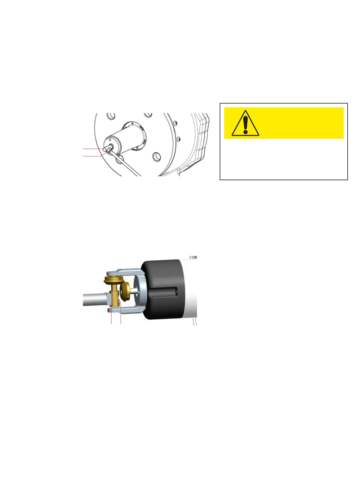
4.1.2 LB version (axial)
Insert the arm into the slot (Fig.15/A) on the
backside shaft with and block it with the M5 nut
(Fig.15/B).
Figure 15
LIQUID LEVEL INDICATOR - INSTRUCTION MANUAL