13
TRANSFORMER COMPONENTS
4.2 Liquid level indicator: general
information
VERIFY CONTACT SURFACE OF THE
CONSERVATOR. IT MUST BE WELL LEVELED
WITH A GOOD DEGREE OF ROUGHNESS (RA=3.2
MICROMETER).
VERIFY AND IN CASE REMOVE ALL WELDING
BURRS TO ENSURE THAT THE WELDING WILL
NOT INTERFERE WITH THE HOUSING FLANGE
HOLES.
DURING THE FLANGE ASSEMBLY, ABB ADVICE
TO APPLY A FEW DROPS OF CYANOACRYLATE
GLUE ON THE GASKET TO FIX IT AT THE OIL
LEVEL FLANGE. THIS ACTION GUARANTEES A
GOOD GASKET POSITIONING AND IT
FACILITATES THE ASSEMBLY
APPLY A SPECIFIC TIGHTENING TORQUE (MAX
20 NM) ON THE NUTS FOLLOWING A CROSS
SEQUENCE.
CAUTION
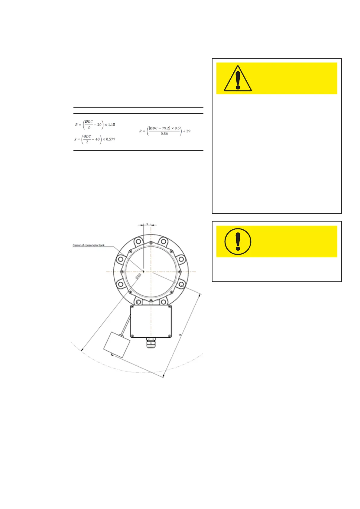
Depending on the conservator design, the level
gauge can have different values of the parameters R
and S (Fig.16) according to the table 4.
Table 4 a
- “S”: parameter that indicates an offset from the vertical conservator
axis [mm]. It is available for LA (radial) configuration.
- “R”: parameter that indicates the length of the rod [mm]. It is available
for LA (radial) and LB (axial) configurations.
- “ØDC”: conservator diameter [mm].
Figure 16
FOR THE LB CONFIGURATION ABB ADVICE TO FIT
IT IN THE CENTER OF THE CONSERVATOR (S=0
MM)
NOTE
LA LB
—
4. Installation