A
B
A
B
D
C
14
LIQUID LEVEL INDICATOR - INSTRUCTION MANUAL
—
4. Installation
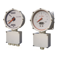
4.3 Comem L140
Insert the arm with float through the machined hole
on the conservator. Place the o-ring on the slot
behind the gauge. Insert the device on the threaded
pin of the conservator flange (Fig.17/A). The oil level
indicator has to be mounted using the items
(Fig.17/B) showed in the table 4b.
Figure 17
Q.ty Description Reference standard
-
Table 4b
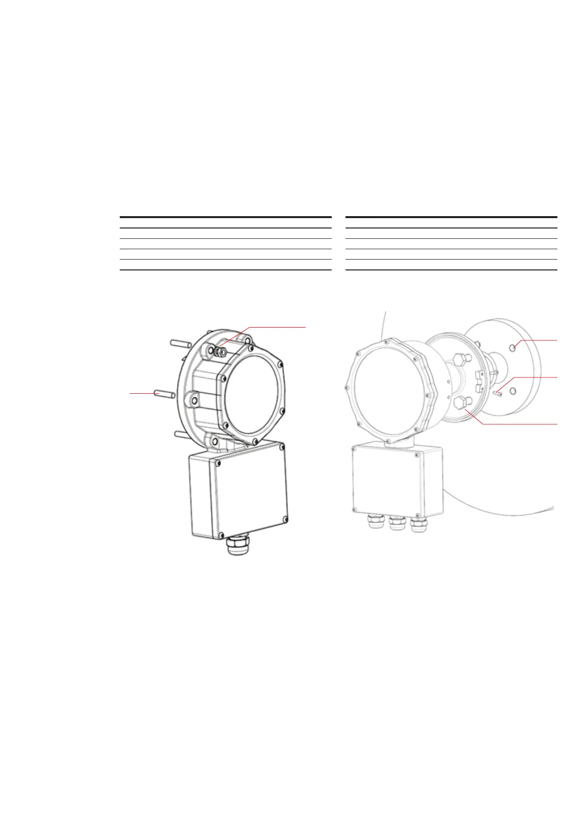
4.4 Comem OLI / Comem eOLI
Place the o-ring on the slot behind the gauge
(Fig.83/B) . Align the flange (Fig.18/C - stud length:
(depending on the conservator flange type). The
gauge has to be assembled on the flange using four
screws M4x12 (Fig.18/D). The oil level indicator
flange has to be assembled using the items showed
in the table 5.
Q.ty Description Reference standard
-
Table 5
Figure 18