DCS800 Firmware manual supplement for North America (rev. 2.60, 2.70) Rev. b 5/30/2008
5
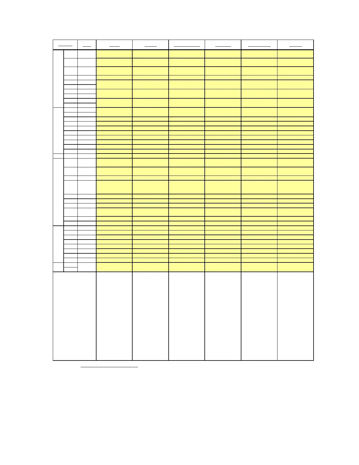
Signal Factory Standard Manual / Const Spd Hand / Auto Hand / Motor Pot Motor Pot
1
90...270 V
AITAC-
------
2
30...90 V
AITAC-
------
3
8...30 V
AITAC-
------
4AITAC+------
5AI1-
6AI1+
7AI2-
8AI2+
9AI3-
10 AI3+
1AI4-
2AI4+
30 V------
4+10 V------
5-10 V------
60 V------
7 AO1 - Motor speed Motor speed Motor speed Motor speed Motor speed
8 AO2 - Arm. voltage act. Actual motor current Actual motor current Actual motor current Arm. voltage act.
9 IACT Actual motor current Actual motor current Actual motor current Actual motor current Actual motor current Actual motor current
100 V------
X5: 1-10 ------
1 DI1 Converter fan ack. Jog1 Jog1*
StartStop
(MainContAck)
Motor pot up Direction
2 DI2 Motor fan ack. Jog2 Jog2*
HandAuto, Speed ref
select
Motor pot down Motor pot up
3 DI3 Main contact. ack. External fault Direction Direction Direction Motor pot down
4 DI4 Off2 (coast stop) External alarm
KpS & TiS to Set1 or
Set2 (24.29)
-
Speed ref. select
(Off=MotorPot;
On=AI1)
Motor pot minimum
5 DI5 E-Stop E-Stop E-Stop E-Stop E-Stop E-Stop
6 DI6 Reset Reset Reset Reset Reset Reset
7 DI7 OnOff1 OnOff1 On Start pulse OnOff1 On Start pulse OnOff1
8DI8
StartStop
MainContAck
StartStop
MainContAck
Off1 Stop pulse NC - Off1 Stop pulse NC
StartStop
MainContAck
9+24 V------
100 V------
1 DO1 Fans On cmd. ReadyRun ReadyOn ReadyOn ReadyOn ReadyRun
2 DO2 Field excit. On cmd. ReadyRef (running) ReadyRef (running) ReadyRef (running) ReadyRef (running) Above limit
3 DO3 Main contact. On cmd. Fault or alarm Tripped (fault) Tripped (fault) Tripped (fault) Fault or alarm
4 DO4 - Zero speed Zero speed Zero speed Zero speed Zero speed
5 DO5 - Above limit Above limit Above limit Above limit At Setpoint
6DO6------
7DO7------
80 V------
1
2
Factory macro.
Resets all
parameters to
default values.
Drive turns on with
maintained input.
Motion is
commanded with
RUN, JOG1, or
JOG2. Run speed
is set with AI-1.
Speed is
controlled by AI-1,
but if Jog1 or Jog2
is set, speed is set
to 23.02 or 23.03.
DI-4 switches to
another set of
tuning values to
run a different
motor. Control is
3-wire.
*Jog inputs do
not initiate
motion, only
change speed.
DI-2 switches
between Hand
(Local I/O) and
Auto
(MainCtrlWord)
mode, and also
switches speed
reference. In
“hand” mode,
speed select is via
AI-1; in “auto”
mode, it is via
parameter 23.01.
Fieldbus module
is required.
Manual control is
2-wire.
DI-4 switches
between Motor
Pot and AI-1 to
select reference
speed. Control is
3-wire.
Speed is always
controlled through
the motor pot up
and down inputs.
Motor pot
minimum speed
can be released
by setting DI-4 to
allow motor pot
down to reduce
speed to zero.
Control is 2-wire.
Main Contact. On Main Contact. On
X96:
X4:
X6:
X7:
Main Contact. On Main Contact. On
-
Speed Reference
-
X3:
- Speed ReferenceSpeed Reference -
--
Terminal #
-
Speed Reference
-
-
-
-
-
-
-
--
-
-
-
Main Contact. On
-
DO8 Relay Main Contact. On
Description
Table 1a: Macro Configurations: The analog and digital inputs and outputs shown in this table are
automatically configured when you implement the macro identified in the top row.
**In revisions prior to 2.6, AI-2 was set to torque limit. AI-2 is unused in rev. 2.6 and higher. If
“torque limit” feature is required, use the new “Torque Limit” macro instead.
***In revisions prior to 2.6, DI-4 controlled “speed reference select.” DI-2 controls this selection in
rev. 2.6 and above, along with selection of hand or auto mode. In “hand” mode, speed select is via
AI-1; in “auto” mode, speed select is via parameter 23.01.