44
Installation and commissioning guide
1ZSC000563-ACF EN, REV. A, 2020-06-25
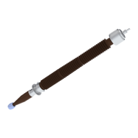
7. Loosen the nut (44).
G006809
8.
Turn the shaft (37) counter clockwise to remove the shaft-socket from the upper draw rod (35).
9.
Remove the hydraulic jack (38) from the bushing.
G006810
10.
Make sure that the draw-rod extension is within
the tolerances:
1. Measure the distance (b).
2. Calculate the extension of the draw rod:
(b) minus (a).
3. Compare the calculated value (b-a) with the
dimension in the table.
NOTE!
Record the values in Measurement
record, page 77, for future reference.
Type Extension
GOE(2) 1175 8.5 mm ±1.0
GOE(2) 1425 9.5 mm ±1.0
GOE(2) 1550 10.5 mm ±1.0
GOE(2) 1675 10.5 mm ±1.0
G006846
End of instruction