The provided document is an Operation Manual for the ABB TPL71-C33 turbocharger, covering its function, technical specifications, usage, and maintenance.
Function Description
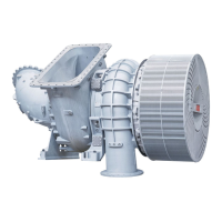
The ABB TPL71-C33 turbocharger is a turbomachine designed for turbocharging internal combustion engines. It consists of a turbine and a compressor, both mounted on a common shaft.
Operation:
Exhaust gases from the diesel engine flow through the gas inlet casing and nozzle ring to the turbine wheel. The turbine wheel utilizes the energy from these exhaust gases to drive the compressor wheel. The compressor then draws in fresh air, compresses it, and forces it into the engine cylinders. The exhaust gases are subsequently expelled to the atmosphere through an exhaust gas pipe connected to the gas outlet casing. The compressed air, essential for the diesel engine's operation, is drawn through the suction branch or filter silencer into the compressor wheel, passes through the diffuser, and exits the turbocharger through the compressor casing.
The rotor operates within two radial plain bearings, one located in the bearing bush and the other in the axial thrust bearing at the compressor end. These plain bearings are connected to a central lubricating oil duct, which receives oil from the engine's lubricating oil circuit. The oil outlet is always situated at the lowest point of the bearing casing.
Compressor Wheel Cooling System (Optional):
Depending on its application, the turbocharger may be equipped with a compressor wheel cooling system. This system delivers cooled compressor air, after passing through the charge air cooler at the engine end, to cool the compressor wheel. This cooling is crucial for ensuring the reliability and extending the replacement intervals of the compressor wheel, especially under specific operating conditions. In versions with compressor wheel cooling, the cooling air is supplied through a side connection in the bearing casing.
Important Technical Specifications
The rating plate provides specific operating limits and recommended replacement intervals for the turbocharger components.
Operating Limits:
- Turbocharger Type: TPL71-C33
- Serial Number: HT846477
- Maximum Compressor Speed (nMmax): 425 1/s
- Maximum Turbine Inlet Temperature (tMmax): 650 °C
- Maximum Compressor Speed (nBmax): 425 1/s
- Maximum Turbine Inlet Temperature (tBmax): 620 °C
- Turbocharger Weight: 2040 kg
- Year of Construction: 2021
Oil Supply:
- Oil Filtration: A filter mesh size of ≤0.050 mm is adequate for TPL71-C turbochargers. An additional self-cleaning fine filter can be used.
- Oil Pressure at Measuring Point M (poil,in):
- Permissible (normal operation): 1.3 – 2.5 bar
- Permissible (engine warm-up): 1.3 – 5.0 bar
- Temporarily admissible (< 1h) -> alarm: 1.1 – 1.3 bar
- Not permissible -> emergency stop: 0.0 – 1.1 bar
- Permissible (pre- and post-lubrication, engine stopped): 0.2 – 2.5 bar
- Oil Temperature at Inlet (Toil,inlet):
- Permissible: 30 – 90 °C
- Temporarily permissible (< 1h) -> alarm: > 90 °C
- Not permissible -> stop the engine: > 95 °C
- Not permissible -> do not start the engine (before starting: preheat the oil): < 30 °C
- Oil Temperature at Outlet (Toil,outlet):
- Permissible: ≤ 140 °C
- Temporarily permissible -> alarm: > 140 °C
- Not permissible -> stop the engine: > 160 °C
Noise Emissions:
- The highest sound pressure level of emissions reaches a maximum of 105 dB(A) near the filter silencer and over the entire speed range.
- Prerequisites for observing this limit include a fitted air-inlet system, standard noise-reducing measures, and acoustically insulated bellows at the air outlet by the engine builder.
Module Weights (TPL71-C):
- Filter silencer: 180 kg
- Radial air suction branch: 70 kg
- Compressor casing: 260 kg
- Wall insert: 65 kg
- Diffuser: 35 kg
- Cartridge group: 460 kg
- Turbine diffuser: 60 kg
- Nozzle ring: 13 kg
- Radial gas inlet casing: 150 kg
- Segment: 12 kg
- Axial gas inlet casing: 80 kg
- Complete compressor casing: 360 kg
Usage Features
Intended Use:
ABB turbochargers are specifically designed for turbocharging internal combustion engines. When used on gas engines, the turbocharger must be operated in an engine room classified as "not at risk of explosion" to comply with machinery directives. The turbocharger is intended to be operated with a clockwise direction of rotation as viewed from the turbine end. Operating limits are determined based on engine builder information and are specified on the rating plate. Any unintended applications or operation outside these limits will void warranty claims.
Safety:
- The turbocharger must only be operated within its specified operating limits by trained personnel.
- All statutory regulations for accident prevention and environmental protection must be observed.
- Personal protective equipment (PPE) must be worn as required.
- Any modifications, additions, or conversions that could impair safety require prior approval from ABB Turbocharging.
- Only original ABB parts should be used to ensure safety and prevent damage.
- The turbocharger must be in technically perfect condition and operated according to its intended application.
Speed Measurement:
A speed measuring system continuously monitors turbocharger speed.
- Assembly: If a speed sensor is not fitted, remove the screw plug (42047) from the bearing casing (marked "n"), screw in the speed sensor (86505) to the stop, tighten to the specified torque, and connect the cable connector (86515). The speed sensor has a sealing lip and does not require an additional gasket.
- Speed Differences (Multiple Turbochargers): For engines with multiple turbochargers, the speed difference between the highest and lowest turbocharger must not exceed 3% of nBmax. If exceeded, reduce engine performance immediately to below 70% of nBmax and contact an ABB Turbocharging Service Station.
- Replacing Speed Sensor: Reduce engine performance to idling speed, stop the engine, switch off oil supply, disconnect the cable connector, unscrew the defective sensor, screw in a new sensor, tighten to specified torque, connect the cable connector, and switch on oil supply. Wear heat-resistant safety gloves as the sensor can reach temperatures over 100 °C.
Stopping the Engine:
Allow the engine to run at idling speed for at least 10 minutes before stopping to dissipate heat from the turbocharger through the circulating lubricating oil.
Emergency Operation (Taking out of operation at short notice):
In emergencies, if the diesel engine needs to operate after turbocharger damage, several possibilities exist:
- Locking the rotor: Only permissible in emergencies. The permissible turbocharger speed for an unlocked turbocharger must not exceed 45% of nBmax. The lubricating oil system must remain connected and turned on if the gas inlet cannot be blocked to prevent overheating.
- Fitting the cover plate: Requires a cover plate, gasket, and sleeves (user-provided). The cartridge group must be removed first.
- Shutting off inlets and outlets: Involves fitting cover plates to the compressor casing outlet, gas inlet, and gas outlet.
- Bypass the turbocharger: Applicable to engines with one turbocharger, requires ready connections and pipes for the bypass.
Maintenance Features
Inspection Work:
- Before Commissioning: Check monitoring devices, filter mat for damage, and oil filter for cleanliness. Flush the lubricating system thoroughly with warm oil after initial commissioning and service work, using special running-in filters. Activate the prelubrication device before starting the engine. Check warning plates and ensure protective sheets are removed.
- After Start-up (Idling Speed): Check oil pressure and inlet temperature in oil supply lines. Check all gas, air, and oil lines for leaks.
- When Running Up Engine: Measure speed, oil pressure, charging pressure, exhaust gas temperature (in front of and behind turbine), and air temperature (in front of and behind compressor) at various engine performance levels. Compare values with the acceptance test report.
- After 100 Service Hours: Clean or replace lubricating oil filters.
Servicing Work (General):
- Service work involves visual checks, monitoring, measuring, and functional checks to identify and rectify changes.
- Carry out service work at specified time intervals.
- Unusual loads or harsh environmental factors may require shortened service intervals.
- An inspection by an ABB Turbocharging Service Station is recommended at least 5 years after the last service.
Entries in Engine Logbook:
Regularly record engine performance and speed, air intake temperature, exhaust gas temperature, charge air pressure, pressure drop in charge air cooler, lubricating oil pressure and temperature, turbocharger speed, and pressure loss in air filter.
Service Work Every 8,000 – 16,000 Hours:
- Disassemble turbocharger.
- Measure clearances.
- Clean and inspect turbine and compressor wheels for damage.
- Clean and inspect turbine and compressor casings for cracks and erosion/corrosion.
- Clean bearing casing and blow air through oil ports.
- Clean nozzle ring and check for cracks and erosion.
- Inspect and assess bearing parts and rotor.
Service Work Every 24,000 – 36,000 Hours:
- Disassemble turbocharger.
- Measure clearances.
- Clean and inspect turbine and compressor wheels for damage.
- Clean turbine and compressor casings for cracks and erosion/corrosion.
- Clean bearing casing and blow air through oil ports.
- Clean nozzle ring and check for cracks and erosion.
- Dismantle, inspect, and balance the rotor.
- Replace plain bearings with original ABB Turbocharging parts.
Replacement Intervals for Turbocharger Components:
- Rotating Components: Compressor and turbine wheels have recommended replacement intervals based on centrifugal forces and load cycles, found on the rating plate. Incalculable parameters (e.g., poor lubricating oil quality, unusual loads, rotor unbalance) can shorten these intervals.
- Non-rotating Components: Expected replacement intervals for non-rotating components and bearing parts depend on system-specific operating conditions (e.g., fuel quality, load profile, exhaust gas temperature, turbine cleaning frequency).
- Expected Intervals (TPL71-C):
- Gas inlet casing: 25,000 – 50,000 h (HFO), 50,000 – 100,000 h (GAS/MDO)
- Gas outlet casing: 35,000 – 100,000 h (HFO), 50,000 – 100,000 h (GAS/MDO)
- Nozzle ring: 25,000 – 50,000 h (HFO), 35,000 – 50,000 h (GAS/MDO)
- Turbine diffuser / cover ring: 25,000 – 50,000 h (HFO), 35,000 – 50,000 h (GAS/MDO)
- Other casings: 100,000 h
- Axial bearing components: 24,000 – 36,000 h
- Radial bearing components: 24,000 – 36,000 h
- Turbine blades (due to wear): ≥ 12,000 h (HFO)
Cleaning the Filter Silencer:
- Removing and Cleaning: Remove filter strip (81265). Rinse with water and detergent, or soak if very dirty. Avoid rough treatment. Clean absorption segments (81136) lightly with pressurized air, a soft brush, or moist cloths. Replace heavily contaminated or damaged parts.
- Fitting: Assemble insert units (absorption segments into sheet metal coverings). Install cover grids (81266) and connecting rods (81269). Tighten screws (81272) to 20 Nm and lock nuts (81273) to 40 Nm.
Cleaning the Compressor During Operation (Wet Cleaning):
- Method: Wet cleaning with clean water injected in front of the compressor wheel. Droplets mechanically remove contamination. Do not use salt water or cooling water additives.
- Prerequisites (XC2 - Orifice Plate on Filter Silencer): Engine load 85-100%. Water pressure 2.5 bar. Water injection time 10 sec. Water temperature 5-50 °C. Orifice diameter 2.5 mm. Operate engine for at least 5 minutes after cleaning.
- Prerequisites (XC3 - External Water-Pressure Vessel): Engine load 50-85%. Water temperature 5-50 °C. Water volume 0.4 or 1 dm³.
- Procedure (XC3): Remove sealing plug (X), fill vessel with clean water, screw in plug (X), push valve activator (Y) for 10-15 seconds, wait 5 minutes for drying. Repeat up to two times if necessary.
- V-engines: Parallel cleaning of compressors is recommended.
Cleaning Turbine Blades and Nozzle Ring During Operation (Wet Cleaning):
- Contamination: Caused by soot, molten ash, cinder, incompletely burned fuel, and sodium vanadyl vanadate from heavy fuel oil.
- Interval: Every 50-200 operating hours.
- Method: Wet cleaning using erosion, solubility, and thermal shock effects. Use clean fresh water.
- Prerequisites: Engine load reduced to 10-15%. Turbine inlet temperature stable and below 430 °C. Wait 10 minutes for parts to cool.
- Cleaning Parameters (TPL71-C): Max temperature at start of cleaning 430 °C. Injection time 10 min. Water flow rate at pWater = 3 bar is 24 l/min.
- Drying: After cleaning, run engine for at least 10 minutes without changing load to dry the turbocharger. An additional 30 minutes of operation with TTE > 500°C is advisable to prevent corrosion.
- V-engines: Parallel cleaning of both turbochargers is recommended.
Cleaning Components Mechanically:
- Required when operational cleaning is insufficient.
- Only use soft tools (scouring cloths, brushes, wire brushes). Avoid needle guns or impact tools.
- Turbine-end, non-rotating parts: Soak contaminated parts in hot water or brake cleaner. Brush off contamination or use a steam cleaner. Only clean nozzle ring with soft brushes, do not sandblast.
- Cartridge group (compressor end): Use pH-neutral cleaning agents. Clean compressor wheel with a scouring cloth or soft brush soaked in water with household cleaning agent. Dry with compressed air, spray gap with penetrating oil.
- Cartridge group (turbine end): Immerse vertically in cleaning fluid, rotate to soak contamination. Allow at least four hours for soaking. Remove contamination with a soft brush. Submerge in clean water to detach loose particles. Dry with compressed air, spray gap with penetrating oil.
Mothballing Turbocharger:
- Up to 12 months: If TAN < 2 mg KOH/g, no measures needed. If engine oil is replaced by preserving oil and circulated, no measures needed. If TAN > 2 mg KOH/g, remove turbocharger, have rotor and bearing parts removed/refitted by ABB Service Station, clean all parts, oil machined surfaces with anticorrosive oil, reassemble. If rotor turns in stack draught, install blind flange.
- More than 12 months: Turbocharger can remain mounted, or casing mounted with rotor/bearings removed, or completely removed. Close all openings with wooden covers and paraffin paper. Store in dry rooms (40-70% relative humidity, no condensation). Check for corrosion annually; clean and renew protection if rust is found.
Disposing of Turbocharger Components:
Disposal must be environmentally compatible and comply with local regulations.
- Metals: Dispose as scrap metal for recycling.
- Non-metallic materials: Dispose as waste.
- Lubricants: Dispose as waste oil.
- Electronic components: Dispose as electronic waste.
- Thermal insulation: Dispose as hazardous waste. Damaged thermal insulation (glass fibres) requires wearing a respiratory mask, safety goggles, and gloves, avoiding dust formation, and using a vacuum cleaner.