Do you have a question about the ABB HVC and is the answer not in the manual?
Overview of the guide for planning and physical installation of the HVC E-Bus Charger.
Identifies the target audience for this installation guide, including customers and contractors.
Explains the various warning, danger, and caution signs used in the manual.
Outlines critical safety rules and precautions for installation and operation of the charger.
Details the obligations of the owner and site operator for safe charge station operation.
Provides guidelines for safe lifting and moving of heavy equipment components.
Warns about dangerous voltages present in the system conductors and terminals.
Covers essential safety practices during the installation process, including PPE.
Advises on observing local regulations for processing product parts and waste.
Provides contact details for ABB sales, delivery, and service information.
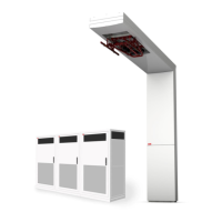
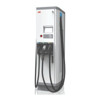
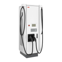
Describes the overall system components and its typical installation configuration.
Lists the components included in the standard delivery configuration with a pole.
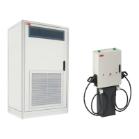
Lists components for the configuration without a pole, for roof or local pole mounting.
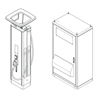
Details the outside and inside views of the Power Cabinet and its main components.
Shows outside and inside views of the ACS Control Module and its connection points.
Illustrates the Junction Box, its cover, and connection points for DC power cables.
Displays the ABB Pole structure and its integrated components like pantograph and sensors.
Lists optional accessories available for order, such as foundations and cable kits.
Describes the pre-fabricated concrete foundation option for the Power Cabinet installation.
Details foundation options for the ABB Pole, including pre-fabricated concrete and tube foundations.
Specifies the glass fiber cable used for communication between components.
Lists essential electrical components like emergency stop buttons and distance sensors.
Outlines the different phases of a HVC E-Bus Charger project from order to operation.
Describes the planning steps involved in the preparation phase before construction begins.
Highlights the importance of obtaining necessary permits and adhering to local regulations.
Details the high current power connection requirements and grid upgrade considerations.
Lists construction work requiring permits, such as base preparation and cable conduits.
Explains the need for internet connectivity for serviceability and remote access.
Specifies requirements for upgrading the electrical grid connection to support the charger.
Defines environmental and physical requirements for the installation location of the charger.
Covers spatial requirements for the Power Cabinet and its surroundings.
Details the minimum footprint and clearance needed for the Power Cabinet, including door opening.
Provides guidance and configurations for placing multiple HVC 150 systems.
Specifies the footprint and clearance requirements for the ABB Pole assembly.
Explains the importance of pole placement for optimal pantograph contact with the bus.
Describes how to align the pole center with the bus's front wheel for correct pantograph positioning.
Defines distances from the curb and accounts for bus kneeling for accurate pole placement.
Specifies the maximum allowed road slope and its impact on pole placement calculations.
Addresses road inclination parallel to the bus drive direction and its effect on pantograph placement.
Covers electrical installation requirements, conductor sizing, and safety regulations.
Details adherence to local safety and electrical regulations for system installation.
Outlines requirements for routing DC power, AC power, GND, and data cables using conduits.
Describes requirements for grounding electrodes and lightning protection for the system.
Introduces the construction phase, including prerequisites like engineering and permits.
Explains options for constructing foundations for the Power Cabinet based on surface type.
Details foundation options: soil with concrete, solid floor with metal frame, or custom built.
Step-by-step guide for installing the Power Cabinet on a pre-fabricated concrete foundation.
Step-by-step guide for installing the Power Cabinet on a metal frame foundation.
Instructions for installing the Power Cabinet on a custom-built foundation footprint.
Details options for constructing foundations for the ABB Pole on soil or solid floor.
Lists foundation types for the ABB Pole: concrete (pre-fab/poured) or tube foundation.
Outlines contractor responsibility for calculating floor load capacity for pole mounting.
Step-by-step process for installing the pre-fabricated concrete foundation for the ABB Pole.
General information on cabling solutions, routing, and marking requirements.
Discusses below-ground cable routing and identity marking.
Provides a diagram showing the overall charge system configuration and connections.
Specifies AC power cable type, shielding, conductor size, and GND conductor requirements.
Lists cables not included in ABB's supply scope, excluding glass fiber cables.
Lists cables between Power Cabinets not included in ABB's supply scope.
Provides detailed specifications for AC, DC, PE, and data cables used in the system.
Outlines the phase for placing and connecting the HVC E-Bus Charger after mechanical work.
Instructions for routing DC power, AC utility, GND, Interlock, and communication cables.
Details the process and precautions for unpacking the Power Cabinet.
Preconditions and notices regarding the unloading and placement responsibility.
Steps for removing packaging material, keys, and mounting hardware from the Power Cabinet.
Describes the two options for moving the Power Cabinet from delivery to its final location.
Step-by-step instructions for lifting and moving the Power Cabinet using a hoist.
Step-by-step instructions for moving the Power Cabinet using a forklift truck.
Covers the process of positioning and securing the Power Cabinet onto its foundation.
Details connecting the Power Cabinet to the foundation using bolts and aligning it with tapped holes.
Instructions on how to unlock and open the Power Cabinet door.
Steps to loosen and move the sliding plates of the cabinet's guidance plates.
Instructions for routing cables through the cabinet's right guidance plates.
Steps to move the sliding plates of the guidance plates and tighten bolts.
Instructions for installing front and rear border covers on the Power Cabinet.
Instructions for installing border covers specific to metal frame foundations.
Steps for placing and securing the front cover plate onto the foundation.
Section on connecting AC power and Ground wires to the Power Cabinets.
Steps to remove protection plates and covers from connector blocks before wiring.
Detailed instructions for connecting the AC power cable's GND wire to the GND rail.
Instructions for stripping, attaching lugs, and connecting AC power cable wires.
Steps to reinstall protection covers and plates after wiring AC power connections.
Procedure for installing optional lightning protection wiring to the GND rail.
Instructions for connecting the GND wire from the Power Cabinet to the ABB Pole.
Procedure for establishing GND connections between multiple Power Cabinets.
Section dedicated to connecting the DC power cables to the Power Cabinets.
Steps to remove protection covers from DC connector blocks before making connections.
Detailed instructions for stripping, attaching lugs, and connecting DC power cables.
Steps to reinstall protection covers after connecting DC power cables.
Covers connecting AC utility, Interlock, and CAN communication cables.
Instructions for routing AC utility, Interlock, and CAN cables to their respective terminal blocks.
Details connecting the AC utility power cable to the circuit breaker and GND rail.
Instructions for connecting the Interlock cable between HVC 150S and HVC 150 master units.
Steps for connecting the CAN communication cable between HVC 150S and HVC 150 master units.
Section for connecting the communication fiber cables to the ACS Control Module.
Instructions for routing communication fiber cables to modules U5 and U7.
Procedure for connecting Ethernet and CAN bus fiber optic cables to ACS modules.
Steps to close and lock the Power Cabinet door after internal connections are made.
Details the contents and initial unpacking steps for the Charge Control Set.
Preconditions and notices related to unloading and preparing the Charge Control Set components.
Steps for removing packaging foil, wooden box contents, and keeping hardware.
Instructions and safety warnings for moving the ABB Pole assembly to its installation location.
Step-by-step guide for mounting the vertical frame of the ABB Pole onto the foundation.
Instructions for lifting and attaching the horizontal frame to the vertical frame of the ABB Pole.
Covers connecting GND wires from various sources to the ABB Pole assembly.
Procedure for connecting the GND wire from the ACS GND to the pole's GND rail.
Instructions for connecting the GND wire from the horizontal frame to the pole's GND rail.
Procedure for connecting the GND wire from the Junction Box to the pole's GND rail.
Instructions for connecting the GND wire from the Power Cabinet to the pole's GND rail.
Steps for installing optional lighting protection wires to the vertical frame's connection points.
Section for connecting various cables to the ACS Control Module.
Diagram showing gland types and their corresponding cable assignments for the ACS Control Module.
Instructions on how to unlock and open the door of the ACS Control Module.
Procedure for connecting DC+ power cables to the ACS Control Module, avoiding PCB damage.
Instructions for connecting DC- power cables to the Junction Box via cable glands.
Details connecting the AC utility power cable from the Power Cabinet to the circuit breaker.
Steps for connecting communication cables, including fiber optics, from the Power Cabinet.
Instructions for routing and connecting the WiFi cable to the WiFi connector.
Guide for connecting RFID Ethernet and Power cables to their respective modules.
Connecting various other cables like Pantograph heater, Interlock, EMO, Beacon, and sensor cables.
Steps to close and lock the door of the ACS Control Module after connections.
Instructions for installing U-profiles and cover plates onto the vertical frame of the ABB Pole.
Procedure for filling the space around the pole base with non-shrink grout for stability.
Outlines the requirements and planning steps before the HVC Charger can be commissioned.
Explains the Customer Acceptance Form process after commissioning, including remaining items.
States that maintenance is performed according to a schedule outside this document's scope.
Provides guidelines for cleaning the Power Cabinet and ABB Pole to maintain the coating condition.
Lists all electrical specifications for the complete HVC system, including input and output parameters.
Provides detailed mechanical dimensions, weights, and impact protection ratings for components.
Details environmental specifications such as ingression protection, temperature ranges, and humidity.
Lists system certifications, including UL compliance and class of protection.
Detailed dimensional drawings of the Power Cabinet.
Detailed dimensional drawings of the ACS Control Module.
Detailed dimensional drawings of the Junction Box.
Detailed dimensional drawings of the ABB Pole structure.
Detailed drawings of the concrete foundation for the Power Cabinet.
Detailed drawings of the metal frame foundation for the Power Cabinet.
Detailed drawings of the pre-fabricated concrete foundation for the ABB Pole.
Shows outlines of the Power Cabinet with different foundation types.
Provides a schematic diagram of all signal connections within the system.
Illustrates the grounding scheme for the entire HVC E-Bus Charger system.
| Output Current | Up to 500 A |
|---|---|
| Efficiency | >95% |
| Output Voltage | Up to 1000 VDC |
| Charging Standard | CCS |
| Cooling Method | Liquid cooled |
| Protection Features | Overvoltage, overcurrent, short circuit, overtemperature |
| Weight | Varies depending on configuration |