IM300 Intelligent Power Monitoring Instrument
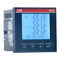
28 29 30 31 32
DI1 DI2 DI3 DI4 COM
24VDC
fig. 2-2-4 Digital inputs wiring diagram
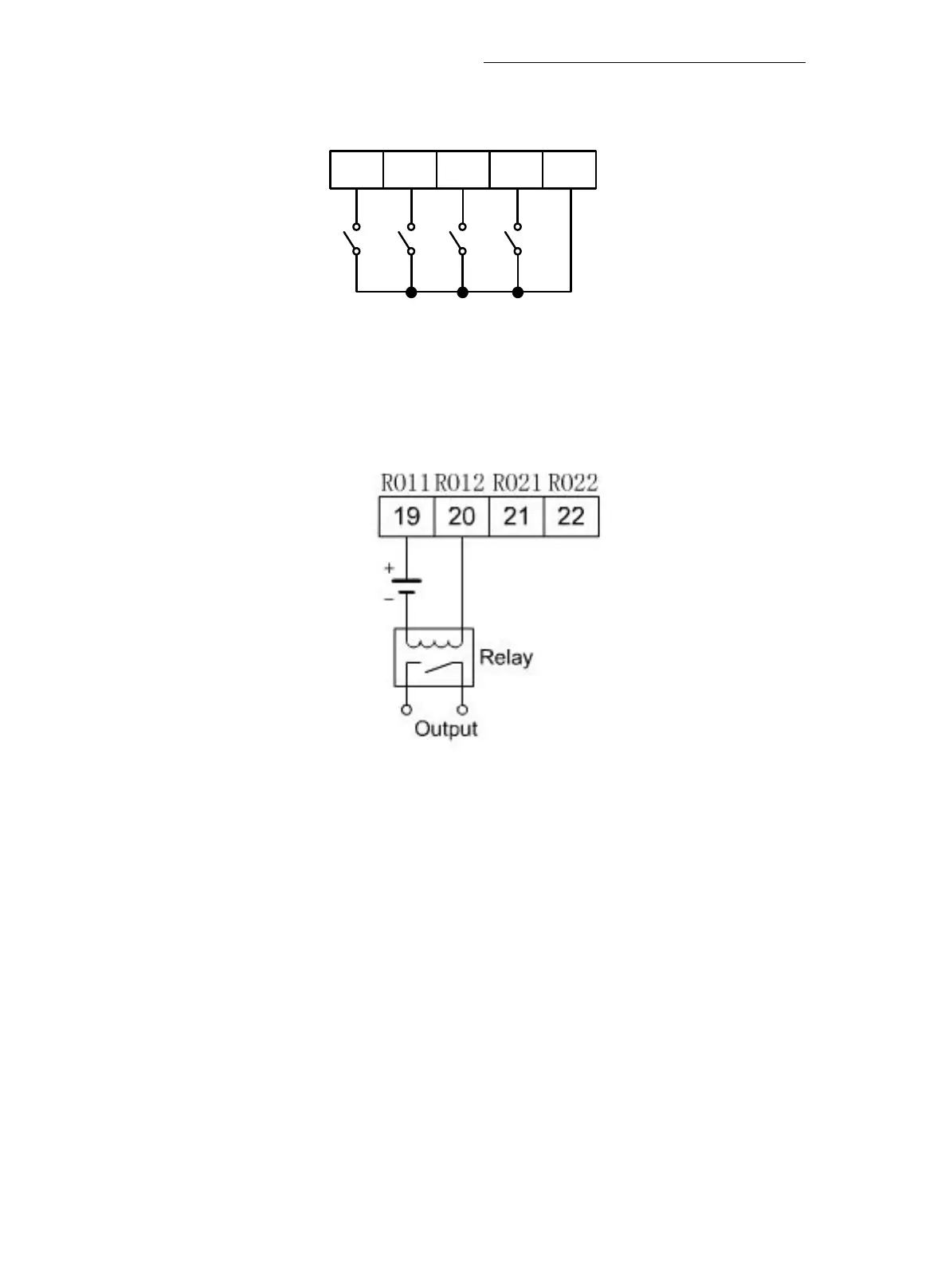
2.2.6. Relay wiring
Control relay outputs node capacity 5A / 30VDC or 5A / 250VAC. When the
load current is greater than the above value should use intermediate relay. Wiring
as shown in fig. 2-2-5.
fig. 2-2-5 Relay wiring diagram.
IM300 provides "always maintain the output" and "pulse output" in two
relay output modes, see "Parameter Settings seventh screen" description.
2.2.7. DC 4 ~ 20mA analog outputs wiring
DC 4 ~ 20mA analog outputs is optically isolated output, maximum isolation
voltage 500VDC. Maximum load resistance RL 600Ω (including line resistance),
open-circuit voltage u is not greater than 24V, wiring is shown in fig. 2-2-6.