EasyManua.ls Logo

ABB IM300-I - Wiring and Configuration

ABB IM300-I
109 pages
Print Icon
To Next Page IconTo Next Page
To Previous Page IconTo Previous Page
Loading...
IM300 Intelligent Power Monitoring Instrument
6
2.2. Wiring and Configuration
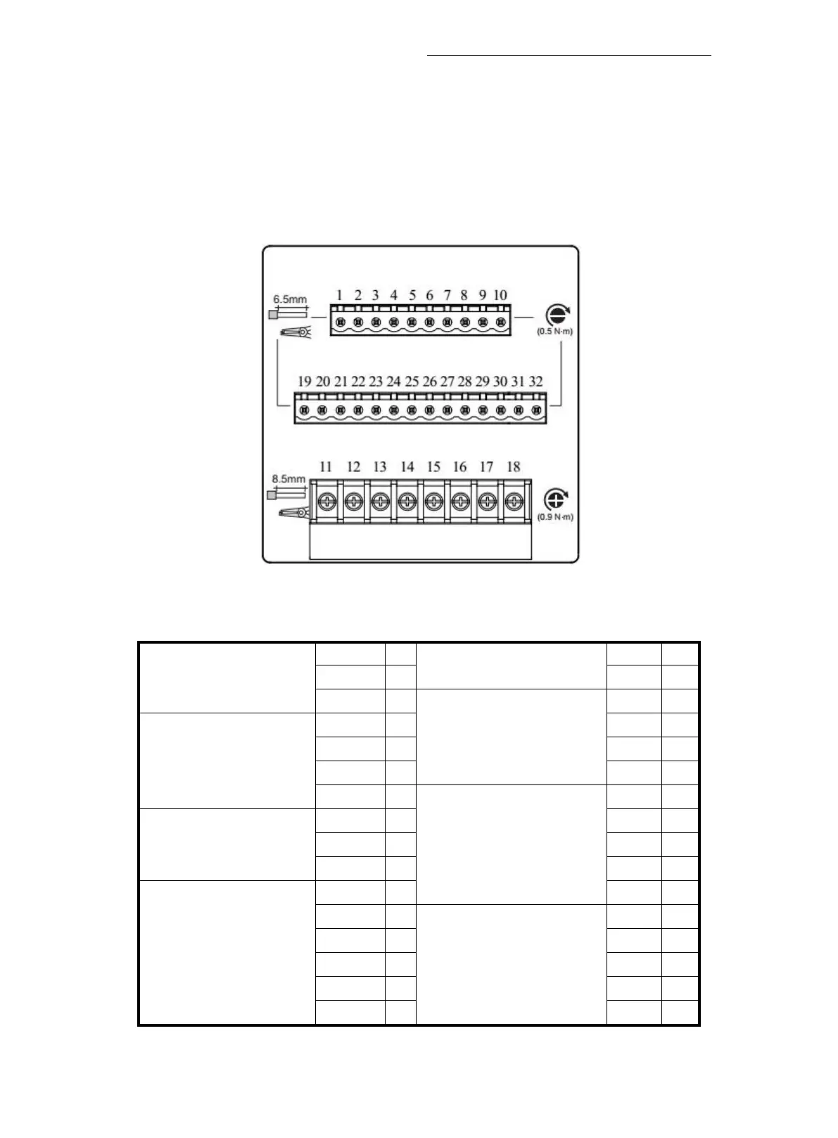
2.2.1. Terminal Definition
IM300 back of a total of three sets of terminals, terminal diagram shown in fig.
2-2-1:
Fig 2.2.1. Terminals fig. (back view)
The definition of the terminals shown in table :
Power Supply
PE
1
I41
17
L
2
I42
18
N
3
Relay Outputs
RO1
19
Voltage Inputs
U1
4
RO1
2
20
U2
5
RO2
1
21
U3
6
RO2
2
22
Un
7
Analog Outputs
NC
23
Communication
SHIEL
D
8
AO+
24
RS+
9
AO-
25
RS-
1
0
NC
26
Current Inputs
I11
1
1
NC
27
I12
1
2
Digital Inputs
DI1
28
I21
1
3
DI2
29
I22
1
4
DI3
30
I31
1
5
DI4
31
I32
1
6
COM
32

Related product manuals