IM300 Intelligent Power Monitoring Instrument
Note: ① IM300 device varies according to the specific models (see appendix C. Order
description). The corresponding terminals that do not have functions are empty (NC).
② In the 3-phase 4-wire system, the Un is connected to the voltage common end; In
3-phase 3-wire system, the Un is connected to B-phase voltage. DI means Digital
Input; RO means Relay Output;Transmitter output is self-powered, AO + is forward
current output , AO- is reverse current output.
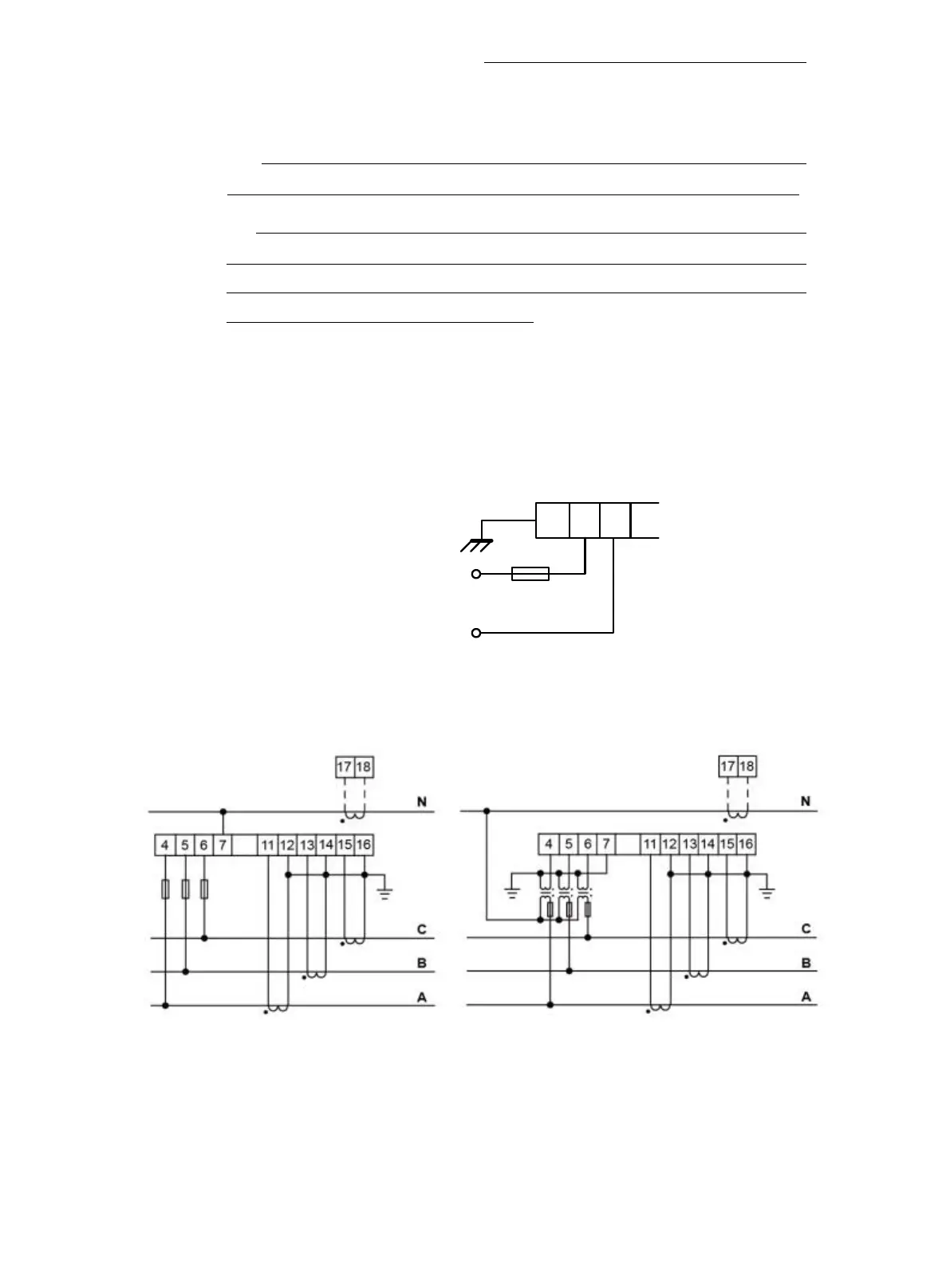
2.2.2. Power supply wiring
Power supply range of IM300 is 85 ~ 265VAC or 85 ~ 265VDC, it
suggested a independent power supply wiring as shown in fig. 2-2-2.
1 2 3
2A fuse
Supply voltage
85~265VAC/DC
Earth
PE L N
Fig 2.2.2. Power wiring diagram
2.2.3. Electric wiring
3-phase 4-wire system: 3CT
Fig 2.2.3.1 3P4W+3CT
3-phase 4-wire system: 1CT