Introduction 11
Basic installation procedure
Here are the basic installation steps described in this guide. The following chapters provide more
details.
1 Access and properly secure the installation site (vessel depressurization and cool down, mains power
down, etc.) (see page 16).
2 Attach the probe to the head-coupler assembly (see page 19).
3 Slide the probe in the vessel and attach the assembled LWT system on the external flange (see
page 21).
4 Ground the head unit and connect it to the mains (see page 27).
5 Power up (see page 28) and configure the instrument (see page 39).
Modbus-specific considerations
Using the Modbus® protocol allows devices made by different manufacturers to exchange information
via the same communication bus without the need for any special interface devices. Up to 32 devices
can be connected on one Modbus line. The Modbus network can be expanded using repeaters.
NOTICE
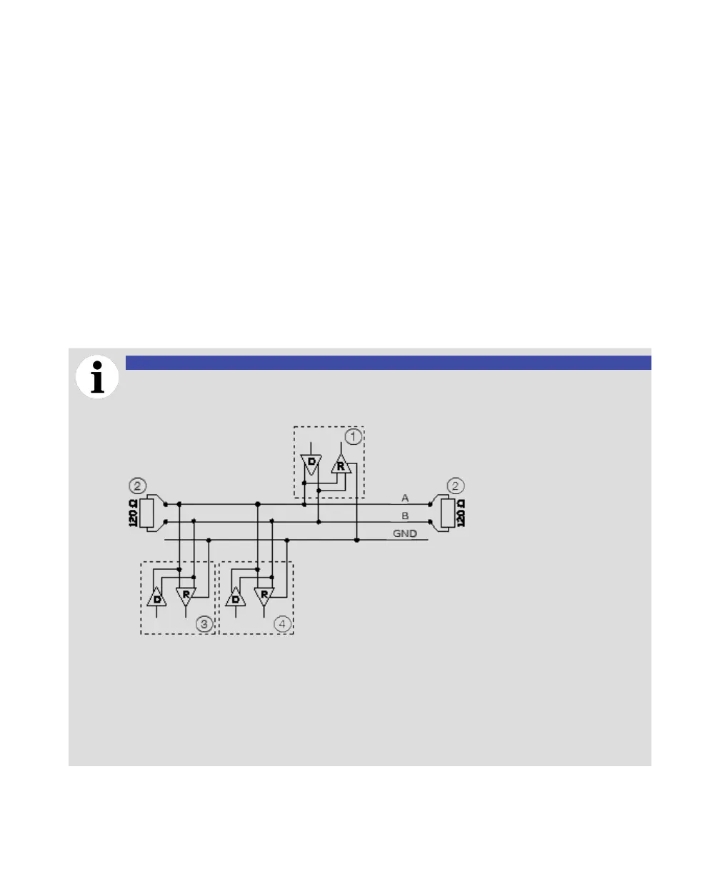
All Modbus networks must be terminated. In this case, each end of the network needs a
1 Modbus master
2 Terminating resistor
3 Modbus slave 1
4 Modbus slave 32
Star or daisy chain configurations are not allowed under any circumstances.
See also “Modbus protocol disclaimer” on page 6.

 Loading...


