30 User Guide
5 From the connection cable:
a Connect the ground cable to the internal PE terminal (if necessary)
b Connect the Modbus cables to the COMM A (+) and COMM B (–) terminals.
c Connect the positive lead to the PWR + terminal, and the negative lead to the PWR – terminals.
6 Plug and seal the electrical connection ports.
7 Put back the housing cover. Turn it so as to seat the O-ring into the housing, then continue
tightening by hand until the cover contacts the housing metal-to-metal.
8 Once installation is complete, make sure that electrical ports are properly sealed against all types of
fluid ingress (rain and/or corrosive vapors or gases) and verify the following:
– Cover installations;
– Locking screw tightness;
– Process connection;
– Electrical connection.
9 Power up the instrument by switching on the circuit breaker.
At power-on, the through-the-glass (TTG) touch interface goes through a calibration process. For the
TTG to work properly, it is mandatory that the housing cover be correctly tightened before power-on.
NOTICE
For instruments equipped with the through-the-glass (TTG) display option, wait for the HMI
calibration process to complete (±30 seconds after power-on) before operating the HMI.
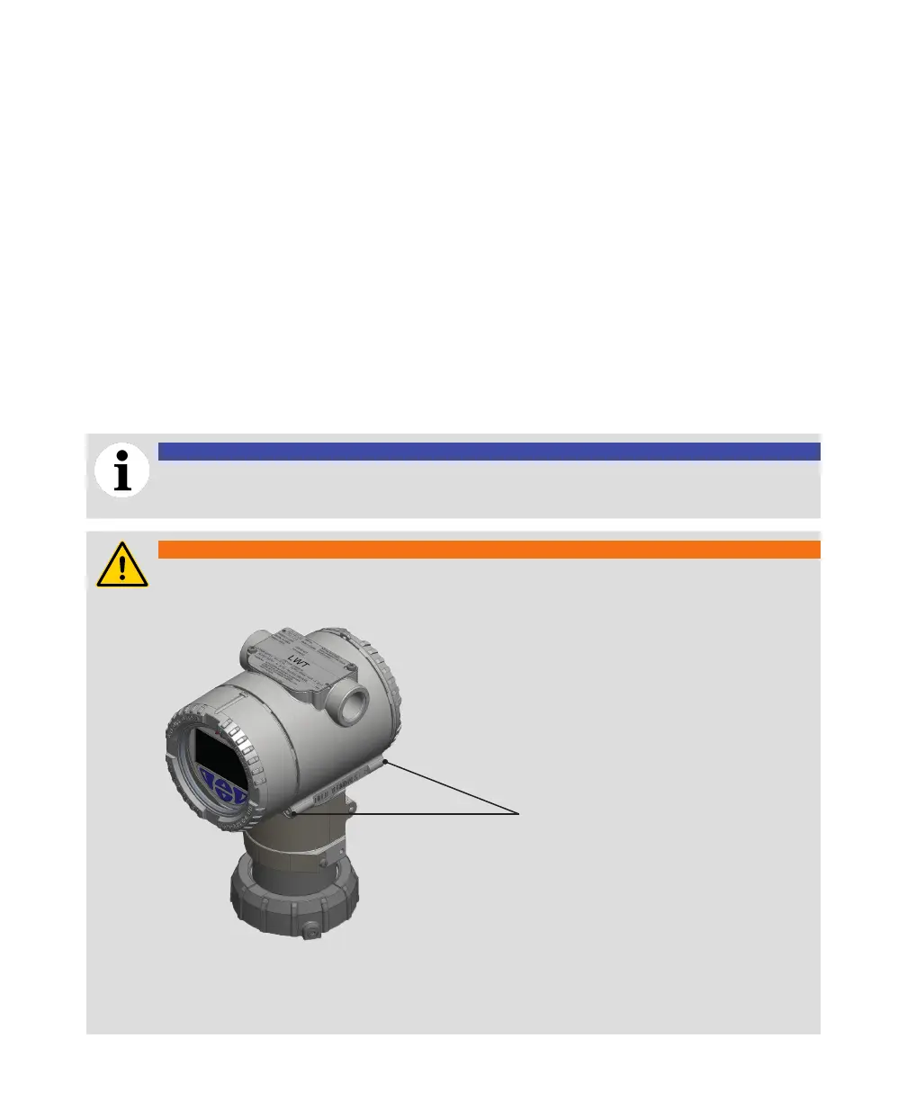
WARNING
Securing housing cover in flameproof/explosion proof areas
Both sides of the electronics housing feature a M4 hex head locking screw on the bottom side.
M4 hex head
locking screws
To secure a housing installed in a hazardous location:
1 Tighten the housing covers by hand.
2 Turn both locking screws counterclockwise until their head stops at the housing cover.

 Loading...


