3GZF500730-70 rev. C RU-EN 01-2016 | ABB Motors and Generators EN – 49
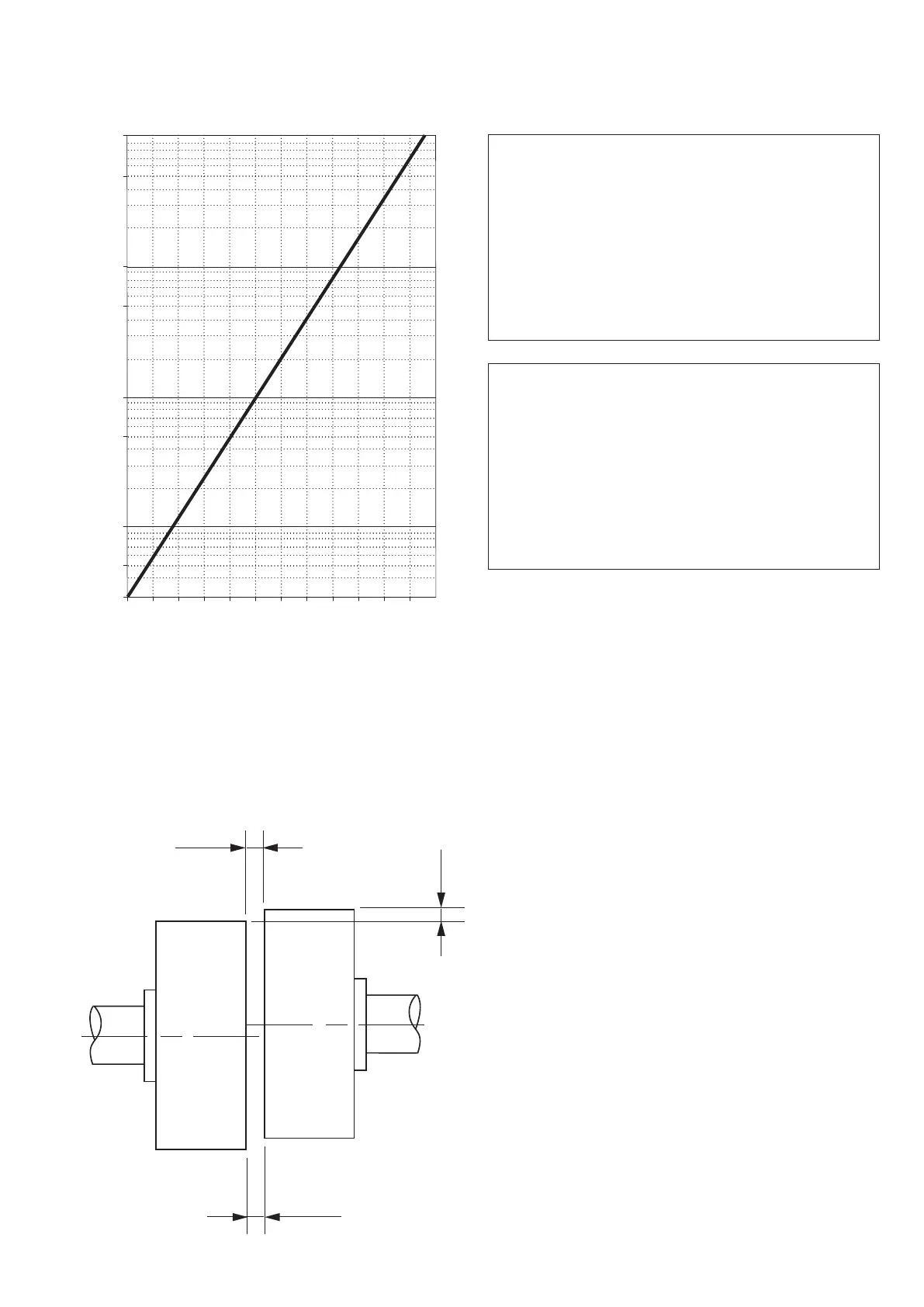
Figure 1. Diagram illustrating the insulation resistance dependence from the temperature and how to correct the
measured insulation resistance to the temperature of 40 °C.
Figure 2. Mounting of half-coupling or pulley
50
10
5
1.0
0.5
0.1
0.05
-10 40 60 70 80 90 10030100 20 50
1)
Key
X-axis: Winding temperature, Celsius Degrees
Y-axis: Insulation Resistance Temperature Coefficient,
ktc
1) To correct observed insulation resistance, R
i
,
to 40 °C multiply it by the temperature coefficient
k
tc
. R
i 40 °C
= R
i
x
a1
b
a2
Рис. 1. График, показывающий зависимость сопротивления изоляции от температуры и метод приведения
измеренного сопротивления изоляции к температуре 40°C.
Рис. 2. Монтаж полумуфты или шкива
11. Рисунки / Figures
Легенда
Ось X: температура обмотки, градусы Цельсия
Ось Y: температурный коэффициент сопротивления
изоляции, ktc
1) Для приведения измеренного сопротивления
изоляции, R
i
, к 40°C необходимо умножить его на
коэффициент k
tc
. R
i 40 °C
= R
i
x