Erection and
Commissioning
MNS DTR / MNS Service
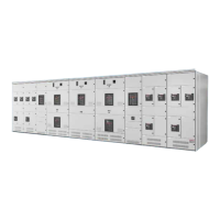
Rys. 33
Montaż ścian tylnej i bocznej
Fig. 33
Mounting of rear and side wall
5. Szyny zbiorcze, jak również szyny ochronne i neutralne należy
przykręcić w miejscach podziału na zestawy transportowe przy
użyciu elementów łączących dostarczonych w dostawie (patrz
Rys. 34/35). Dozwolone jest użycie tylko śrub ze środkiem za-
bezpieczającym przed odkręcaniem ESLOK* oraz podkładek
stożkowych. Miejsca połączeń szyn zbiorczych są dostępne
przez zdejmowane ściany działowe pomiędzy przedziałem kablo-
wym a przedziałem szynowym. Ściany te muszą być założone po
wykonaniu połączenia szynowego. Otwory fasolkowe na końcach
szyn gwarantują tolerancję odchyłek połączenia. Przy prawidło-
wym wyrównaniu zespołów transportowych otwory te pokrywają
się. Dodatkowe wiercenie szyn jest niedopuszczalne z powo-
du powstawania wiórów. Powierzchnie styków nie wymagają
żadnego przygotowania. W przypadku zabrudzenia należy prze-
trzeć je czystą szmatką. Nie wolno używać szczotki metalowej ani
chemikaliów. W przypadku podwójnego systemu szyn należy je
fazować (po obu stronach 45
+0
-0,5
z tolerancją 1
+1
-0,5
mm). Roz-
dział 5.14 zawiera dopuszczalne momenty dokręcające połączeń
śrubowych szyn.
6. Przewód ochronny (PE lub PEN) należy podłączyć do szyny PE
lub PEN. Dodatkowe podłączenie do centralnego uziemienia roz-
dzielnicy jest możliwe w dowolnym miejscu otworowanej szyny PE
i PEN biegnącej wzdłuż rozdzielnicy. Należy przy tym uwzględnić
miejscowe normy.
7. Uchwyty transportowe muszą być usunięte. Otwory po uchwytach
należy zaślepić zaślepkami GMN 775 502 P18.
* połączenia wykonane za pomocą środka ESLOK można zdemonto-
wać i dokręcać do 10 razy zachowując odpowiednie parametry dokrę-
cania. Alternatywą dla środka ESLOK jest użycie lakieru zabezpiecza-
jącego Loctite270.
Uwaga: Śruby pokryte środkiem Loctite270 muszą być dokręcane z
odpowiednim momentem dokręcającym tuz po pokryciu śrub tym
środkiem. Utwardzenie powłoki łączącej rozpoczyna się ok. 5 minut od
początku montażu. Po tym czasie kolejne korekty lub ustawienia,
dokręcanie i odkręcanie śrub jest niedozwolone. Po czasie około 2
godzin od momentu montażu, śruba jest odpowiednio zabezpieczona
przed naprężeniami dynamicznymi. Połączenie osiąga docelową
wytrzymałość po około 8-12 godzinach w pomieszczeniu o temperatu-
rze 20°C.
Po usunięciu z połączenia śruby pokrytej środkiem Loctite270 pozo-
stałości środka muszą być usunięte z tego połączenia/gwintu. Ponadto
w takim przypadku należy koniecznie użyć nowych śrub i nakrętek.
5. The busbars as well as the protective and neutral conductor
bars have to be bolted at the transport divisions using the
connections provided (see fig. 34/35). Only ESLOK-sealed
screws together with one conical spring washer each are
to be used. The connecting points for the busbars are
accessible through partition wall between the cable and
busbar compartments. This partition wall must be closed after
the bars have been secured. Elongated holes at the ends of
the bars ensure adequate adjustment within the tolerances
set. lf the erection is properly carried out the holes will match
up as required. Drilling is not permissible, due to the
resulting chips. Contact surfaces do not need a special
pretreatment. In case of dirt, the contact surfaces should be
cleaned with a soft cloth. Do not use a metal brush or
chemical liquids. In case of double busbar systems, the bars
should be deburred or slightly phased (on both sides
45°
+0
-15
with 1
+1
-0,5
mm). Refer to chapter 5.14 for
tightening torques for bolted connections of busbars,
protective and neutral conductor bars.
6. The protective conductor (PE or PEN) is to be connected
to the PE/PEN bar. Additional connections to the central
earthing system can be made at any point of the perforated
PE/PEN bar. Local regulations must be complied with.
7. The lifting angles may be removed and afterwards the
fastening holes have to be plugged with plug
GMN 775 502 P18.
* Connections with polyamide (ESLOK) securing varnish can be
dismantled and retightened up to 10 times and still offering suffi-
cient thread locking effect. Alternative to ESLOK is liquid securing
varnish Loctite270.
Remark: The screws coated with Loctite270 must be used mme-
diately after coating and be tightened with the correct tightening
torque. The curing of the coating starts just 5 minutes after as-
sembly. After this period no further adjustments or settings are
possible. A subsequent tightening or release of the screw is not
admissible.One up to two hours after assembly, the screw is
adequately locked against dynamic stresses. The joint reaches
final strength after 8 up to 12 hours at the latest at room tempera-
ture (20°C).
If a screw coated with Loctite270 was released out of the thread,
the cured adhesive surface must be completely removed out of
the thread. For the renewed assembly a new screw has to be
used absolutely.
Wkręt samogwintujący M6x10
Self tapping screw M6x10