+DC1
+DC2
COM
COM
RSTP
FRNT
VPN
ON
DC1
DC2
1
2
1
1
10/100/1000
10/100/1000
10/100 Base-TX
POWER
CONSOLE
IO
2
3
4
5
6
7
8
2
3
4
1
5
6
7
8
2
3
4
3BSE08315922
Section 3 Interface Modules
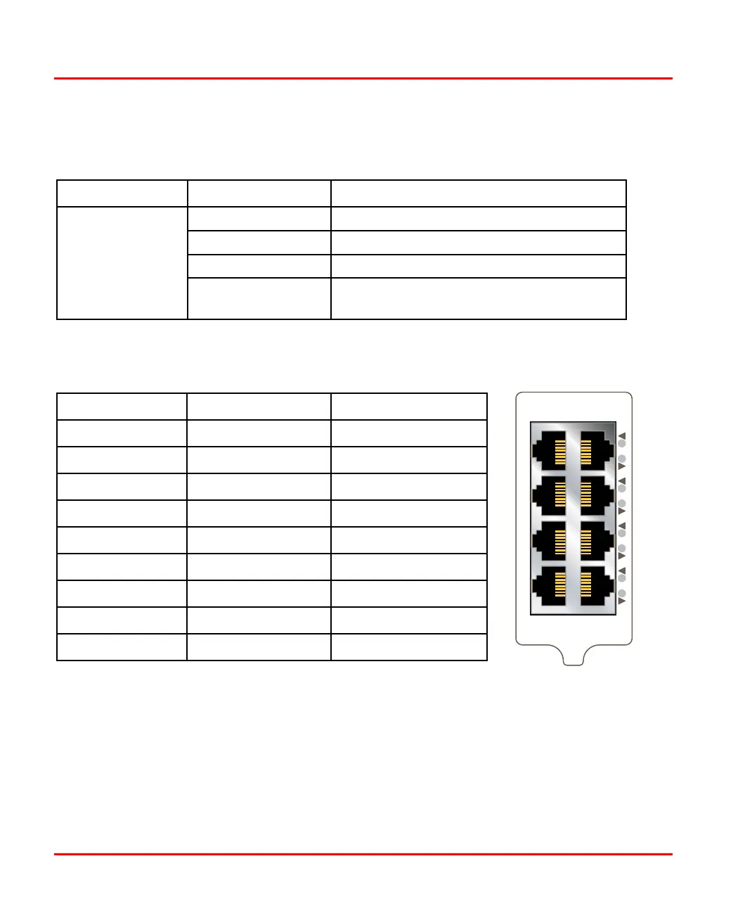
LED Indicators 8-Copper Ports
Figure 9. LED Indicators 8-Copper Ports
* Direction relative this unit.
LED Status Description
Copper ports 1 – 8 OFF No Link
GREEN Link established
GREEN FLASH Data trafc indication
YELLOW Port alarm and no link. Or if FRNT, RSTP or
Link Aggregation mode, port is blocked.
Position Direction* Description
1 In/Out
TD+
2 In/Out
TD–
3 In/Out
RD+
4
– Not connected
5
– Not connected
6 In/Out
RD–
7
– Not connected
8
– Not connected
Shield In/Out Connected to PE