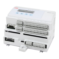
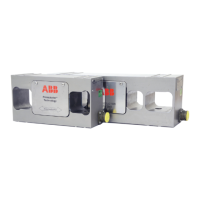
Tension Electronics PFEA111/112, User Manual
Table of Contents
3BSE029380R0101 Rev C v
CONTENTS (continued)
Appendix C - PFTL 301E - Designing the Load Cell Installation
C.1 About This Appendix...............................................................................................C-1
C.2 Basic Application Considerations............................................................................C-1
C.3 Step-by-Step Guide for Designing the Load Cell Installation .................................C-2
C.4 Installation Requirements ........................................................................................C-3
C.5 Mounting Alternatives, Calculating Force and Calculating Wrap Gain..................C-4
C.5.1 Horizontal Mounting...............................................................................C-4
C.5.2 Inclined Mounting...................................................................................C-5
C.6 Force Calculation for Measurement with a Single Load Cell .................................C-6
C.6.1 The Most Common and Simple Solution ...............................................C-6
C.6.2 Force Calculation when the Web is not Centered on the Roll ................C-7
C.7 Mounting the Load Cells .........................................................................................C-8
C.7.1 Routing the Load Cell Cable ..................................................................C-8
C.7.2 Connecting the Load Cell Extension Cable............................................C-8
C.8 Technical Data .........................................................................................................C-9
C.9 Cable Diagram 3BSE028140D0065, Page 1/5, Rev. C .........................................C-11
C.10 Mounting Instruction, Cable Connector, 3BSE019064, Rev. A ............................C-12
C.11 Dimension Drawing, 3BSE019040D0094, Rev. C................................................C-13
C.12 Assembly Drawing, 3BSE019040D0096, Rev. C .................................................C-14
Appendix D - PFRL 101 - Designing the Load Cell Installation
D.1 About This Appendix...............................................................................................D-1
D.2 Basic Application Considerations............................................................................D-1
D.3 Step-by-Step Guide for Designing the Load Cell Installation .................................D-2
D.4 Installation Requirements ........................................................................................D-3
D.5 Load Cell Orientation Depending on Measurement Direction................................D-4
D.6 Mounting Alternatives, Calculating Force and Calculating Wrap Gain..................D-5
D.6.1 Horizontal Mounting...............................................................................D-5
D.6.2 Inclined Mounting...................................................................................D-6
D.7 Force Calculation for Measurement with a Single Load Cell .................................D-7
D.7.1 The Most Common and Simple Solution ...............................................D-7
D.7.2 Force Calculation when the Web is not Centered on the Roll ................D-8
D.8 Mounting the Load Cells .........................................................................................D-9
D.8.1 Mounting with Brackets........................................................................D-11
D.8.2 Mounting Screws for the Load Cells ....................................................D-12
D.8.3 Routing the Load Cell Cable ................................................................D-12
D.9 Technical Data .......................................................................................................D-13
D.10 Cable Diagram, 3BSE028140D0065, Page 3/5, Rev. C ........................................D-15
D.11 Cable Diagram, 3BSE028140D0065, Page 4/5, Rev. C ........................................D-16
D.12 Dimension Drawing 3BSE004042D0003, page 1/2, Rev. O.................................D-17
D.13 Dimension Drawing, 3BSE004042D0003, page 2/2, Rev. O................................D-18
D.14 Dimension Drawing, 3BSE026314, Rev. - ............................................................D-19
 Loading...
