PositionMaster EDP300 | CI/EDP300-EN Rev. C 15
M10420-02
2
1
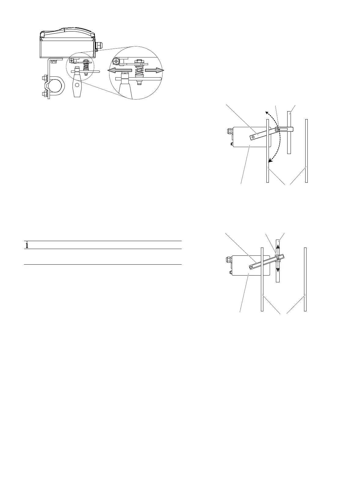
Fig. 10: Positioner linkage
1 Increasing linkage 2 Reducing linkage
The scale on the lever indicates the link points for the various
stroke ranges of the valve.
Move the bolt with the follower pin in the oblong hole of the
lever to adjust the stroke range of the valve to the working
range for the position sensor.
Moving the link point inwards increases the rotation angle of
the position sensor. Moving the link point outwards reduces
the rotation angle of the position sensor.
Adjust the actuator stroke to make use of as large an angle of
rotation as possible (symmetrical around the center position)
on the position sensor.
Recommended range for linear actuators:
-30° … 30°; minimum range: 25°
NOTICE
After mounting, check whether the positioner is operating
within the sensor range.
Position of actuator bolt
The actuator bolt for moving the potentiometer lever can be
mounted permanently on the lever itself or on the valve stem.
Depending on the mounting method, when the valve moves
the actuator bolt performs either a circular or a linear
movement with reference to the center of rotation of the
potentiometer lever. Select the chosen bolt position in the HMI
menu in order to ensure optimum linearization. The default
setting is as follows:
Fig. 11: Actuator bolt on lever (rear view)
1 Potentiometer lever 2 Actuator bolts c Valve spindle
d Valve lamp e Positioner
Fig. 12: Actuator bolt on valve (rear view)
1 Potentiometer lever 2 Actuator bolts c Valve spindle
d Vent lamp e Positioner
M11031
1 2 3
5 4
M11032
1 2 3
5 4