PositionMaster EDP300 | CI/EDP300-EN Rev. C 27
6.7.2 Connection on the device
M10132-01
2
3
NPT1/4"
G1/4"
Y2
OUT 2
Y1
OUT 1
SUP/ZUL
IN
1
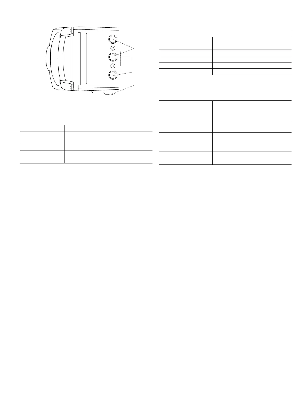
Fig. 26: Pneumatic connections
1 Pneumatic outputs 2 Supply air
3 Filter screw (on underside of housing)
Marking Pipe connection
SUP / ZUL IN Supply air, pressure 1.4 ... 10 bar (20 ... 145
psi)
Y1 / OUT1 Output pressure for actuator
Y2 / OUT2 Output pressure for actuator (2nd connection
with double-acting actuator)
Join the pipe connections according to the designation,
observing the following points:
— All pneumatic piping connections are located on the right-
hand side of the positioner. G1/4 or 1/4 18 NPT tap holes
are provided for the pneumatic connections. The
positioner is labeled according to the tap holes available.
— We recommend that you use a line with dimensions of 12
x 1.75 mm. The level of supply air pressure required to
apply the actuating force must be adjusted in line with the
output pressure in the actuator.
— The working range for the positioner is between
1.4 ... 10 bar (20 ... 145 psi).
6.7.3 Air supply
Instrument air
1)
Purity Maximum particle size: 5 m
Maximum particle density: 5 mg/m
3
Oil content Maximum concentration 1 mg/m
3
Pressure dew point 10 K below operating temperature
Supply pressure 1.4 … 10 bar (20 … 145 psi)
Air consumption
2)
< 0.03 kg/h / 0.015 scfm
1) Free of oil, water and dust in accordance with DIN / ISO 8573-1. Pollution and
oil content according to Class 3
2) Independent of supply pressure
Compressed air output
Range 0 ... 10 bar (0 ... 145 psi)
Air capacity Standard:
40 kg/h = 31 Nm
3
/h = 20 scfm
Optional:
50 kg/h (40 Nm
3
/h / 23 scfm)
Output function For single or double-acting actuators
Air is vented from actuator or actuator is
blocked in case of (electrical) power failure
Shut-off values
End position 0 % = 0 ... 45 %
End position 100 % = 55 ... 100 %