26 Quick Installation Guide - PVS-175-TL “A.1 Version”
EN
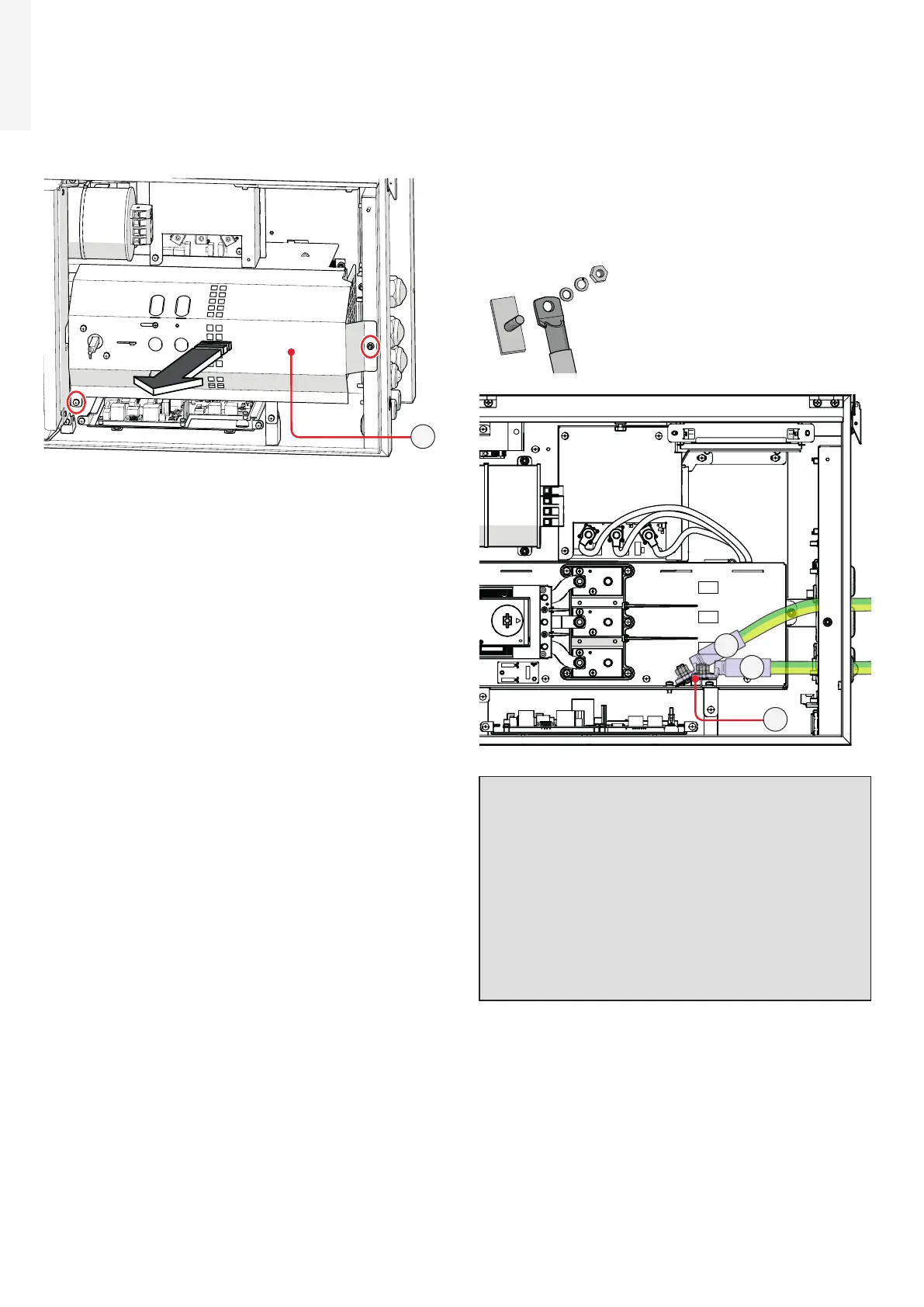
Follow the procedure below to route all the cables:
• Open the wiring box front cover (07).
• Remove the AC protective shield (23) by removing
the M5 screw and the M5 nut.
23
Depending on the ground connection method
(internal (28) or external (10)) follow the procedures
described below:
Internal ground connection
• Pass the protective earth cable through the
proper cable gland (12) on the AC panel.
• Fix the protective earth cable lug to the protection
earth connection point (int.) (28) using the
washers and bolt pre-installed on the M10 stud,
as shown in the following diagram:
1 = cable lug
2 = flat washer
3 = spring washer
4 = M10 nut
1
2
3
4
RST
B
A
28
ATTENTION – A Depending on the version of
the AC panel installed on the inverter it will be
necessary to use a different protection earth
connection point in order to avoid mechanical
stress due to cable bending: in case of Single-
core AC panel use the horizontal connection
point (A), otherwise in case of Multi-core AC
panel it will be necessary to use the oblique
connection point (B).
ATTENTION – A The cable lug must be
installed with a tightening torque of 21Nm.

 Loading...


