27
EN
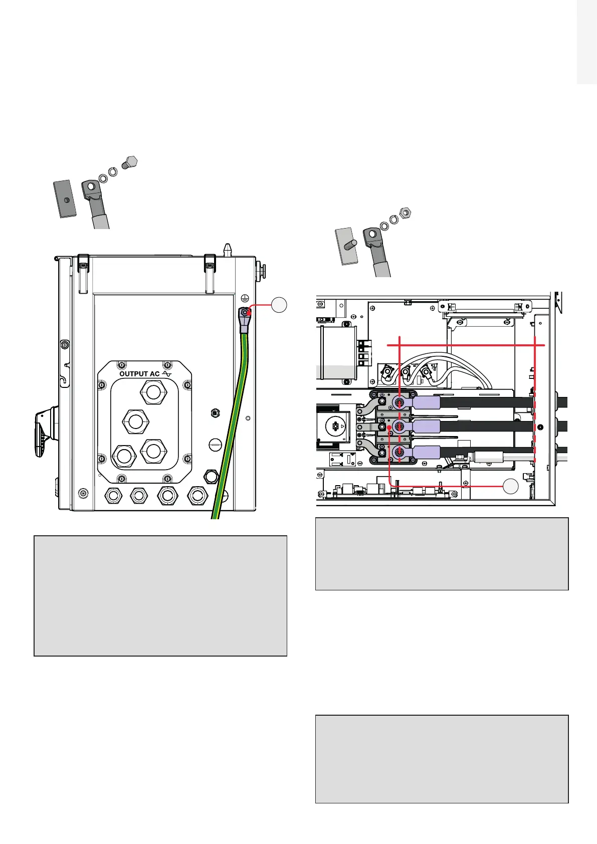
External ground connection
• Fix the protective earth cable lug to the protection
earth connection point (ext.) (10) (this is the same
thread for handles) using the washers and M8
bolt provided in the wiring box installation kit, as
shown in the following diagram:
1 = cable lug
2 = flat washer
3 = spring washer
4 = M8 bolt
1
2
3
4
10
ATTENTION – A The cable lug must be
installed with a tightening torque of 15.2 Nm.
ATTENTION – A Before connecting the
inverter to AC or DC sources use a suitable
multimeter to test the conductivity of the
earth connections between the protection
earth connection point (ext.) (10) and a
handles thread (04) on the housing of power
module.
AC line connection
• Pass the AC cables through the cable glands (11)
on the AC panel. The lenght of phase cables on
the internal side of wiring box need to be about
300 mm (cable lug included).
• Fix the R, S and T cable lugs to the AC
connection busbars (27), paying attention to the
correspondence of the phases with the labels,
using the washers and the M10 nuts pre-installed
on the busbar as shown in the following diagram:
1 = cable lug
2 = flat washer
3 = spring washer
4 = M10 nut
1
2
3
4
RST
R
300mm
S
T
27
ATTENTION – A In case of a wrong phase
sequence the inverter will not connect to the
grid and it will provide an error state.
ATTENTION – A The cable lugs must be
installed with a tightening torque of 25Nm.
• Re-install the AC protective shield (23) by using
the M5 screw and the M5 nut previously removed
with a tightening torque of 3 Nm.
• Check the tightness of the AC cable glands (11)
(5 Nm for single core AC cable gland M40 / 18 Nm
for multi core AC cable gland M63) and, if used,
protective earth cable gland (12) (5 Nm for PE
cable gland M32) at the end of the installation.
ATTENTION – A In case of the AC cable
glands (11) was accidentally removed during
the cable routing phase, it will needed to
assure the correct tightness of the lock nut
of the cable gland to the inverter chassis with
a tightening torque of 8.0 Nm (for each cable
gland).

 Loading...


