X1Zx+XNZx
X
R (Ohm/loop)
50%
80%
1
2
3
4
5
6
7
8
9
10
11
80% of RLdFw
40% of RLdFw
RFPEZx
12
13
alt. 80% of
RFPEZx (Load
encroachment)
120°
20°
a
IEC05000369-4-en.vsdx
IEC05000369 V4 EN-US
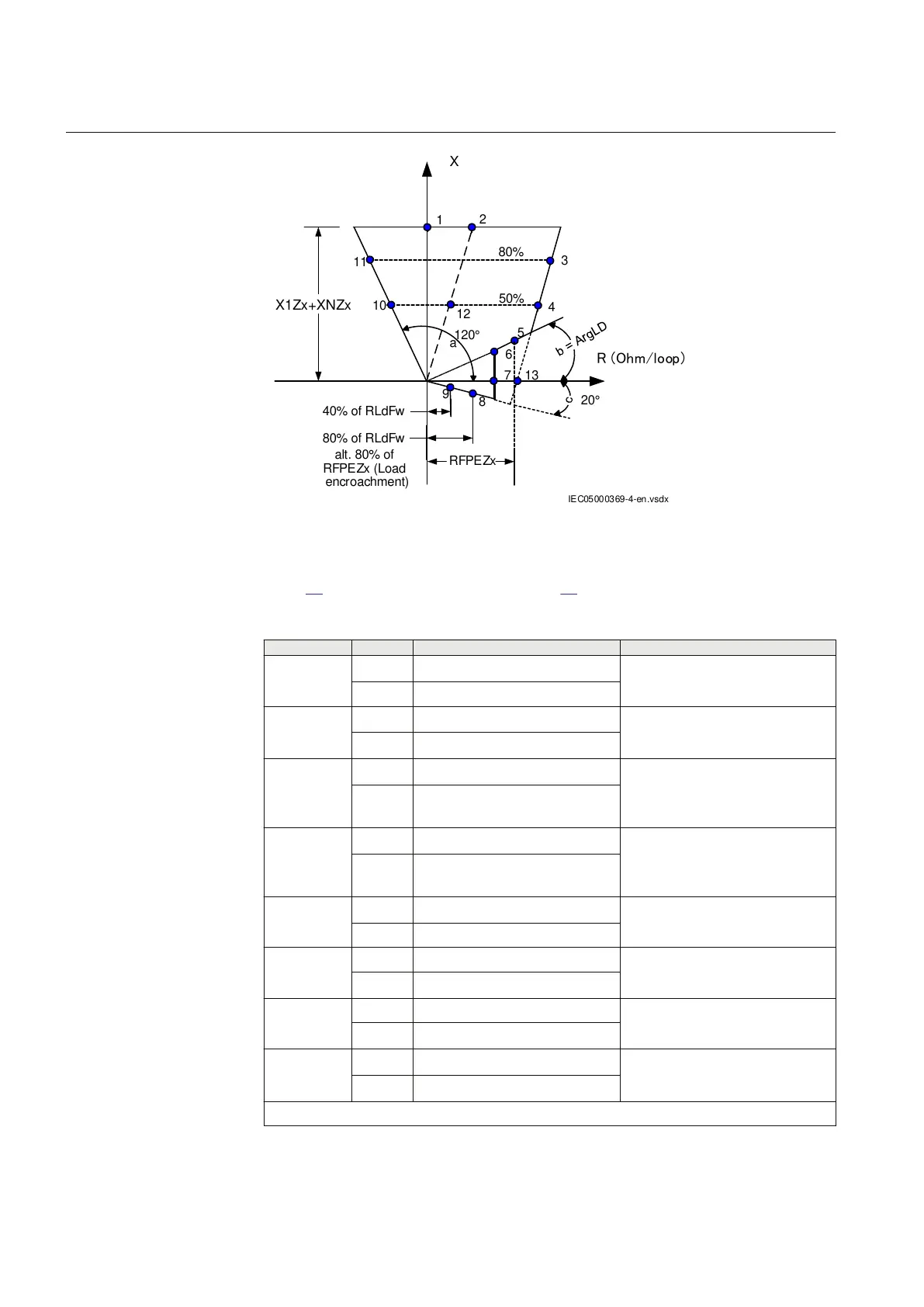
Figure 24: Distance protection characteristic with test points for phase-to-
earth measurements
Table
21 is used in conjunction with figure 24.
Table 21: Test points for phase-to-earth L3-E (Ohm/Loop)
Test point Reach Value Comments
1 X (2 x X1
set
+X0
set
)/3
R 0
2 X (2 x X1
set
+ X0
set
)/3
R 2 x R1
set
+ R0
set
)/3
3 X 0.8 x (2 x X1
set
+ X0
set
)/3
R 0.8 x (2 x R1
set
+ R0
set
)/3
+RFPE
set
4 X 0.5 x (2 x X1
set
+ R0
set
)/3
R 0.5 x (2 x R1
set
+R0
set
)/3 +
RFPE
set
5
X 0.85 x RFPE
set
x tan(ArgLdset) ArgLd = angle for the maximal load
transfer
R 0.85 x RFPE
6 X RLdFwset x tan(ArgLdSet)
R RLdFw
set
7 X 0
R RLdFw
set
8 X –0.1072 x RLdFw
set
Exact: 0.4 x RFPE x tan
(ArgDir=20°)
R 0.4 x RLdFw
set
Table continues on next page
Section 11 1MRK 505 378-UEN A
Testing functionality by secondary injection
116 Line differential protection RED670 2.2 IEC
Commissioning manual