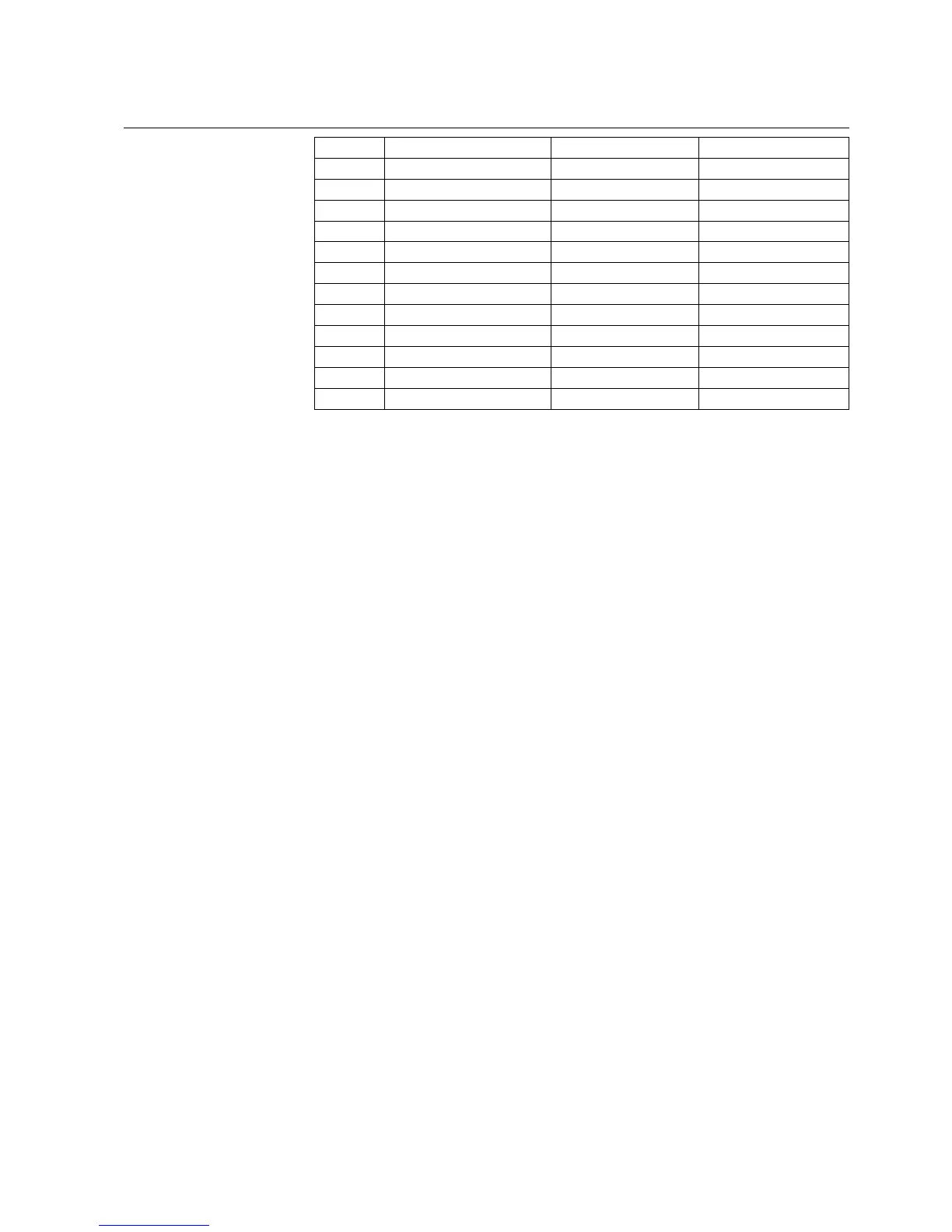
77
12 T8/1
13 T4/3
14 T2/B T2/2
15 T6/3
16 T7/B T7/2 T7/A
17 T4/B T4/2
18 T2/3
19 T6/B T6/2
20 T7/R T7/3 T7/B
21 T4/R T4/1
22 T2/R T2/1
23 T6/R T6/1
24 T7/1
B: Black wire for voltage transformer.
R: Red wire for voltage transformer.
1: 1 A input for current transformer.
2: Common input for current transformer.
3: 5 A input for current transformer.
Example:
To determine the pins for the analog input module 1VCF750170R0817: 3CTs,
3VTs, 1CTs; used with transformers with 1 A on the secondary windings.
The following connection must be done:
Analog input 1; the current transformer for phase 1 must be connected on pins 11
and 3 (common).
Analog input 2; the current transformer for phase 2 must be connected on pins 22
and 14 (common).
Analog input 3; the current transformer for phase 3 must be connected on pins 10
and 2 (common).
Analog input 4; the voltage transformer for phase 1 to earth must be connected on
pins 21 and 17.
Analog input 5; the voltage transformer for phase 2 to earth must be connected on
pins 5 and 1.
Analog input 6; the voltage transformer for phase 3 to earth must be connected on
pins 23 and 19.
Analog input 7, for the toroidal transformer for the residual current must be
connected on pins 24 and 16 (common).
Multifunction Protection and Switchgear Control Unit
Operator's manual
REF 542plusREF 542plus
1MRS755869