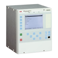
1. Verify the local HMI setting AutoEnerg to be Off and ManEnerg to be DBLL.
2. Set the parameter ManEnergDBDL to On.
3. Apply a single-phase voltage of 30% GblBaseSelBus to the U-Bus and a single-
phase voltage of 30% GblBaseSelLine to the U-Line.
4. Check that the MANENOK output is activated after set tManEnerg.
5. Increase the U-Bus to 80% GblBaseSelBus and keep the U-Line equal to 30%
GblBaseSelLine. The outputs should not be activated.
6. Repeat the test with ManEnerg set to DLLB with different values on the U-Bus
and the U-Line voltage.
6.9.1.4 Testing the voltage selection
Testing the voltage selection for single CB arrangements
This test should verify that the correct voltage is selected for the measurement in the
SESRSYN function used in a double-bus arrangement. Apply a single-phase voltage
of 30% GblBaseSelLine to the U-Line and a single-phase voltage of 100%
GblBaseSelBus to the U-Bus.
If the UB1OK or UB2OK inputs for the fuse failure are used, they must be activated,
during tests below. Also verify that deactivation prevents operation and gives an
alarm.
1. Connect the signals above to binary inputs and binary outputs.
2. Connect the voltage inputs to the analog inputs used for each bus or line
depending of the type of busbar arrangement and verify that correct output
signals are generated.
6.9.1.5 Completing the test
Continue to test another function or end the testing by setting the parameter TestMode
to Off under Main menu/Tests/IED test mode/TESTMODE:1. If another function
is tested, then set the parameter Blocked to No under Main menu/Tests/Function test
modes/Control/SESRSYN(25,SYNC)/SESRSYN:X for the function, or for each
individual function in a chain, to be tested next. Remember to set the parameter
Blocked to Yes, for each individual function that has been tested.
6.9.2 Interlocking
Prepare the IED for verification of settings as outlined in
5.1 "Preparing the IED to
verify settings".
Values of the logical signals are available on the local HMI under Main menu/Tests/
Function status/Control/<Function>/<Function:1>. The Signal Monitoring in
PCM600 shows the same signals that are available on the local HMI.
Section 6 1MRK 502 049-UEN A
Testing functionality
106
Commissioning manual

 Loading...