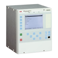
6.4.4 Out-of-step OOSPPAM
Prepare the IED for verification of settings as outlined in
5.1 "Preparing the IED to
verify settings".
Values of the logical signals for OOSPPAM are available on the local HMI under
Main menu/Tests/Function status/Impedance/OOSPPAM(78)/OOSPPAM:1.
The Signal Monitoring in PCM600 shows the same signals that are available on the
local HMI.
6.4.4.1 Verifying the settings
The commissioning procedure requires only one calculation and it must be done when
all the settings have already been determined. Suppose that the voltages, the currents
and the impedances ForwardR, ForwardX, ReverseR and ReverseX are equal to those
in the example as described in the "Setting guidelines" section for the Out-of-step
protection function in the REG650 Application manual.
1. Calculate the magnitude of a fundamental frequency current I that results in the
measured reactance ForwardX, as shown in point A in Figure 13.
I A U ForwardX
I A kV Ohm
I A
gen
[ ]
=
[ ]
=
[ ]
=
/ /
. / / .
3
13 8 3 0 565
14107
IECEQUATION2321 V1 EN (Equation 1)
2. Three symmetrical fundamental frequency phase voltages must be fed to IED,
with magnitudes proportional to U
gen
/ √(3), that is, taking into the account the
actual PT ratio in the IED. If three symmetrical fundamental frequency currents,
proportional to I = 14107 A, that is, taking into the account the CT ratio, are fed
to the IED, and they all lag their phase voltages by 90 electrical degrees,
OOSPPAM function must measure a reactance equal to ForwardX, that is, 59.33
percent of Zbase, corresponding to 0.565 Ohm. This reactance is constant and
stationary, as shown in point A in
Figure 13. The voltages and the currents must
be calculated to perform the injection by a test set.
Voltages (instantaneous values) of the fundamental frequency, that is, 50 Hz or
60 Hz, must be as follows. Example for fundamental frequency 50 Hz:
u U t
L phase1
2 2 50 0= ⋅ ⋅ ⋅ ⋅ ⋅
( )
sin .
π
IECEQUATION2328 V1 EN (Equation 2)
u U t
L phase2
2 2 50 0 2 3= ⋅ ⋅ ⋅ ⋅ ⋅ − ⋅
( )
sin . /
π π
IECEQUATION2329 V1 EN (Equation 3)
u U t
L phase3
2 2 50 0 4 3= ⋅ ⋅ ⋅ ⋅ − ⋅
( )
sin . /
π π
IECEQUATION2330 V1 EN (Equation 4)
Where U
phase
= U
gen
/ √(3) = 13800 V / √(3) = 7967.4 Volts. The actual PT ratio
must be applied to this primary value of the phase voltage, so that the actual value
of the secondary input voltage applied to IED can be calculated.
1MRK 502 049-UEN A Section 6
Testing functionality
55
Commissioning manual

 Loading...