30
1MRS 751108-MUM
Protection Relay
Technical Reference Manual, General
REX 521
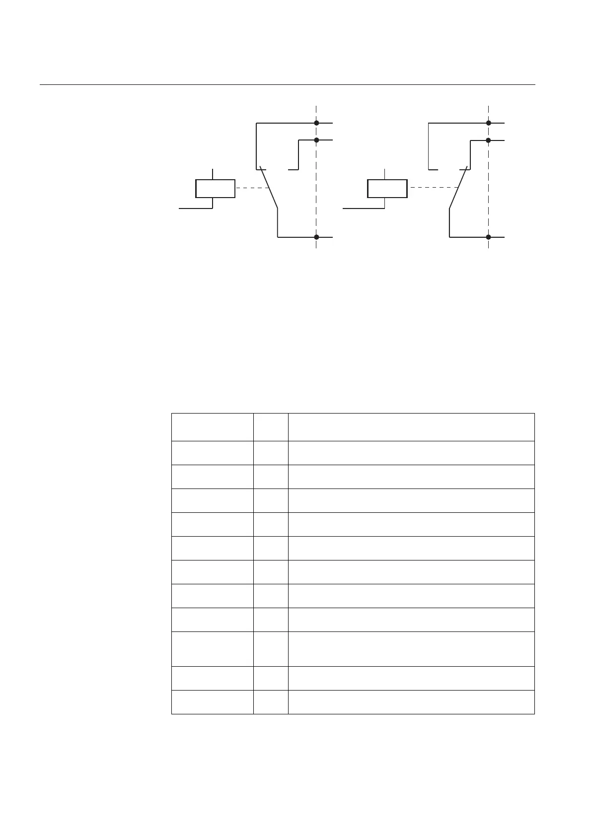
IRFoutputrex
Fig. 4.1.11.1.-1 Self-supervision output (IRF)
When a fault has been detected, the green READY LED indicator starts blinking, a
fault indication text is displayed on the HMI and an event “IRF activated” (E31) is
generated over serial communication.
4.1.11.2. Fault indication texts
The table below shows the different fault indication texts that may appear, the
corresponding fault codes and the actions that should be taken. The fault code is only
used for remote control systems connected to the serial communication.
IRF
IRF
5
4
3
5
4
3
Normal condition
Fault condition
Table 4.1.11.2-1 Fault indications
Fault indication
Fault
code
Reason/Action
INTERNAL FAULT
Relay HSPO1
1 Protection operative, but the faulty output relay cannot be
controlled
INTERNAL FAULT
Relay PO1
7 Protection operative, but the faulty output relay cannot be
controlled
INTERNAL FAULT
Relay PO2
8 Protection operative, but the faulty output relay cannot be
controlled
INTERNAL FAULT
Relay PO3
9 Protection operative, but the faulty output relay cannot be
controlled
INTERNAL FAULT
Relay SO1
15 Protection operative, but the faulty output relay cannot be
controlled
INTERNAL FAULT
Relay SO2
16 Protection operative, but the faulty output relay cannot be
controlled
INTERNAL FAULT
Relay control
20 Protection inoperative. An attempted relay control operation
failed.
INTERNAL FAULT
Relay test
21 Protection inoperative. Two or more relays were found faulty
during test.
INTERNAL FAULT
NOV error
30 Protection operative. Nonvolatile memory error. The corrupted
data cannot be used. May be solved by restoring the factory
settings.
INTERNAL FAULT
EEPROM error
40 Protection inoperative
INTERNAL FAULT
RAM error
50 Protection inoperative