52
1MRS 751108-MUM
Protection Relay
Technical Reference Manual, General
REX 521
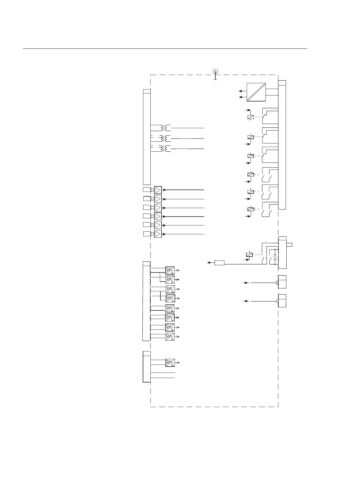
4.2.5. Terminal diagram of REX 521: Sensor
Fig. 4.2.5.-1 Terminal diagram of REX 521: Sensor
1A
5A
1A
0,2A
100V
X1.1
16
15
14
13
12
11
8
7
6
5
4
3
2
1
10
9
19
18
22
21
27
25
24
X2.1
X2.2
X2.3
DIFF
DIFF
DIFF
X2.4
X2.5
X2.6
DIFF
DIFF
DIFF
X4.2
DI1
DI2
DI3
DI4
DI5
DI6
DI7
DI8
5
6
7
8
9
10
11
12
13
14
15
16
17
18
1
2
X3.1
DI9
IRF
3
8
7
6
10
11
9
5
4
SO1
+
-
X4.1
1
2
SO2
12
13
PO1
PO2
PO3
14
15
17
18
TCS1
HSPO1
X4.2
3
4
1
2
Block_HighSensor_a
X3.2
X3.3
CT4
CT5
VT1
I
0
I
0B
*)
U
0
**)
RS-485
DATA A
DATA B
9
10
Voltage input, U
3
Voltage input, U
2
Voltage input, U
1
Current input, I
L2
Current input, I
L3
Sensor
Sensor
Sensor
Sensor
Sensor
Sensor
Current input, I
L1
Mains
ACFail
SERIAL BUS
SERIAL BUS
TempAlarm
VD3
VD2
VD1
RS3
RS2
RS1
**) The jumper is not assembled by default
when the protection relay is delivered
*) Connected to U12b in H01S and H03S