1MRS751802-MUM
REX 521
241
Protection Relay
Technical Reference Manual, Standard Configurations
The high and low alarm signals of the function block AI1 are used when the
measured current level is selected for indicating motor statuses “Stop” and “Runs”.
The settings for the AI1 can be made in
Main menu\Measurements\AI1\Control setting\.
The function block is set in use by using the Limit Selection parameter.
11.8. Incoming feeder, High H08/H09
11.8.1. Features
This application example describes an incoming feeder to a single busbar including:
• Overcurrent protection
• Non-directional earth fault protection
• Overvoltage protection
• Undervoltage protection
This application example is an optional solution for the second application example
(Section 9.2. Incoming feeder, Basic B01), if overvoltage and undervoltage
protection is required or wider range of measurements is needed.
The network is resistance or solidly earthed. The three-phase current measurement
is established with current transformers. The neutral current is measured via a
current transformer located in the neutral earthing circuit on the LV side of the
power transformer. Phase-to-earth voltage measurements are established with
voltage transformers.
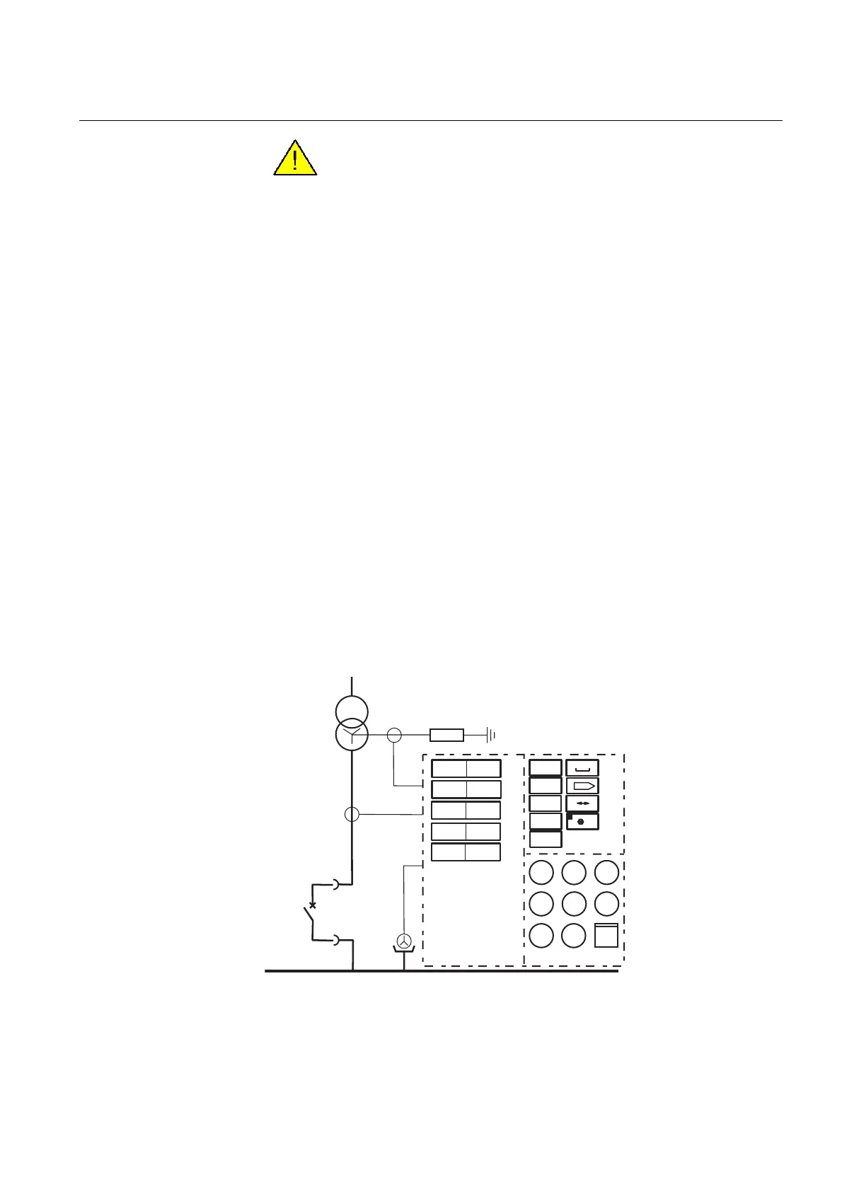
Fig. 11.8.1.-1 H08/H09 is used for protection, measuring and supervision on an
incoming feeder in a single busbar system. The supplying network
is either solidly or resistance earthed
For logical operation of motor status indication, the “Stop” and
“Runs” indications must be selected in pairs and the corresponding
checksums must be added together, for example:
STOP:Ind. and RUNS:Ind. checksum = 24.
REX 521 H08
3U< 27
3U>
59
3I > 50/51
UserIncH08
f
P
3U
3I
Q
E
pf
TCS
CBCM
0
I
MCS
3I~harm
000
R
3U~harm
CBFP
*/62
I >
0
50N/51N
I
0
3U_B
Application Example 15