2105551MNAD | RMC-100 | 11
4.1 Ground the controller
The RMC must be grounded by mounting on a grounded DIN rail.
– Equipment damage. The DIN rail on which the controller is mounted must be
bonded to an earthing terminal. The bonding conductor must have a cross sectional area of at
least 12 AWG or 4 mm
2
.
To ground the DIN rail:
1. Screw the DIN rail onto the mounting surface.
2. Attach a grounding wire to the DIN rail.
3. Attach the other end of the grounding wire to an electrical ground.
4.2 Mount the RMC
To mount the controller on the DIN rail:
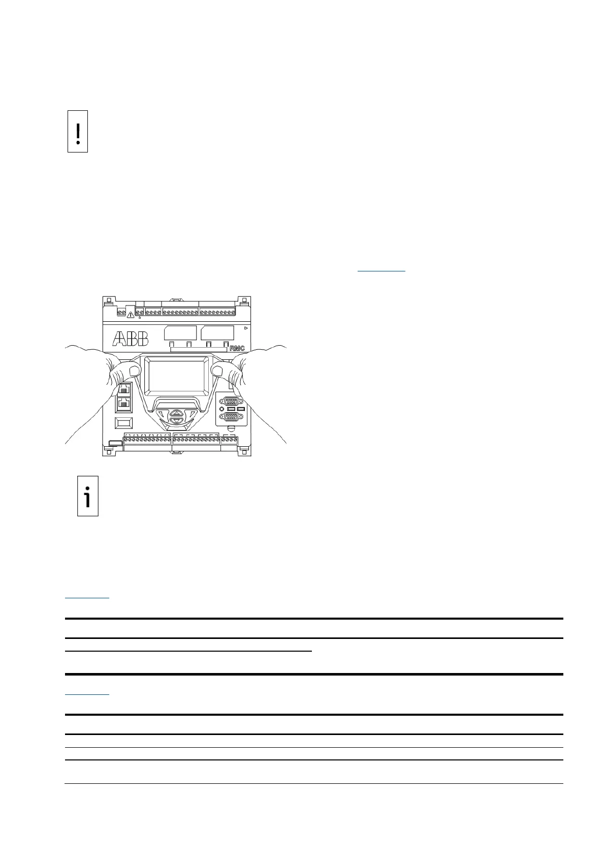
1. Position the RMC on the DIN rail.
2. Push the RMC onto the DIN rail until it snaps into place (Figure 4-1
).
Figure 4-1: Mounting the RMC
To remove the controller, use a slotted screwdriver inserted in the
access slot of the DIN rail release clip to loosen the clip. For more information, refer to the
Maintenance and Service
section in the RMC User Manual.
4.3 Wire COMM ports
Wire the RMC COMM ports to communicate with and power external devices. Wiring for communication
depends on the type of serial interface required by the device. Wiring for power is required if there is no
external supply powering the device.
Table 4-1 provides the specifications for the serial communication ports.
Table 4-1: Serial communication specifications
Terminal connector (9 POS), screw termination and
pluggable COMM module
Active when communication module is inserted
Table 4-2 identifies RS-232, RS-422, and RS-485 communication pinouts for COMM 1 and COMM 2.
Table 4-2: COMM 1 and COMM 2 serial communication pinouts
Switched voltage
(Sw VOUT)
Switched voltage
(Sw VOUT)
Switched voltage
(Sw VOUT)

 Loading...


