EasyManua.ls Logo

ABB RMC-100 - Communication Ports Overview

ABB RMC-100
40 pages
To Next Page IconTo Next Page
To Previous Page IconTo Previous Page
Loading...
16 | RMC-100 | 2105551MNAD
NOTICE
Equipment damage. Do not overtighten the terminal connector screws as this may
damage the wire
.
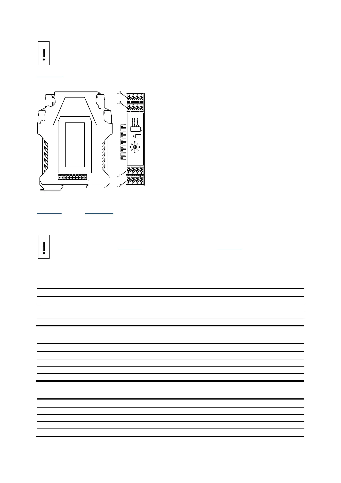
Figure 4-7 shows the side view of a TFIO module and its pinouts.
Table 4-8 through Table 4-13 identify the wiring pins for the TFIO modules used with the RMC. The
wiring pins are the same for legacy TFIO modules.
NOTICE
Equipment damage. The output voltage at the following pins is dependent upon the
external power supply connected to the CHARGER/EXT PWR port:
J2
-1, J4-1 and J4-3 (Table 4-8) and J1-1, J2-1, J3-1, J4-1 (Table 4-9)
Before connecting to these pins, make sure that the external device is compatible with the input
voltage at the CHARGER/EXT PWR port
.
Table 4-8: TFIO valve control interface module
J1
J2
J3
J4
1
POINT 1 SIG
AO Vdc source
POINT 3 SIG
POINT 5 SIG
2
POINT 1 GND
AO Isink
POINT 3 GND
POINT 6 SIG
3
POINT 2 SIG
AO Isource
POINT 4 SIG
POINT 7 SIG
4
POINT 2 GND
AO Vdc common
POINT 4 GND
POINT 8 SIG
Table 4-9: TFIO analog output (4-20 mA) module
J1
J2
J3
J4
1
AO1 Vdc source
AO2 Vdc source
AO3 Vdc source
AO4 Vdc source
2
AO1 Isink
AO2 Isink
AO3 Isink
AO4 Isink
3
AO1 Isource
AO2 Isource
AO3 Isource
AO4 Isource
4
AO1 Vdc common
AO2 Vdc common
AO3 Vdc common
AO4 Vdc common
Table 4-10: TFIO analog input module
J1
J2
J3
J4
1
AI1 (+)
AI3 (+)
AI5 (+)
AI7 (+)
2
AI1 (GND)
AI3 (GND)
AI5 (GND)
AI7 (GND)
3
AI2 (+)
AI4 (+)
AI6 (+)
AI8 (+)
4
AI2 (GND)
AI4 (GND)
AI6 (GND)
AI8 (GND)
Figure
4-7: TFIO module
Side View
Pins
M2

Table of Contents

Other manuals for ABB RMC-100

Related product manuals