RTAC-01 User’s manual 2-1
Chapter 2 – Overview
Overview
This chapter contains a short description of the Pulse
Encoder Interface module, a delivery checklist, and
warranty information.
The RTAC-01
module
The RTAC-01 Pulse Encoder Interface module offers an
interface for a digital pulse encoder connection. A pulse
encoder should be used if accurate speed or position
(angle) feedback from the motor shaft is required.
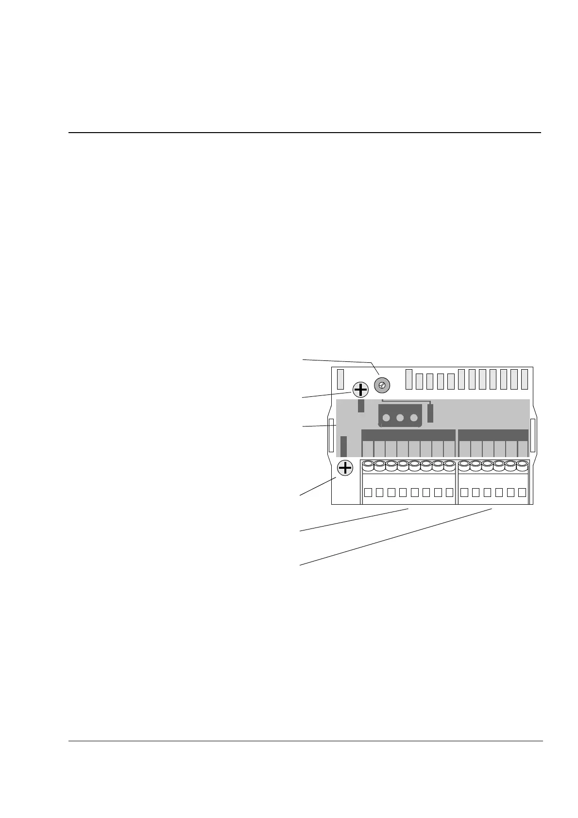
Module layout
65432165432187
Fixing screw (GND)
Node ID selector (S1)
Diagnostic LEDs
Fixing screw
(CHASSIS)
0
8
4
C
2
6
A
E
1
3
5
7
9
B
D
F
Terminal block for
encoder signals (X2)
Terminal block for encoder
power connections (X1)
CHASSIS
GND
NODE ID
SHLD
RTAC-01
PULSE ENCODER INTERFACE
X2
X1
WD/
INIT
CHB
CHA
SHLD
CHA+
CHA-
CHB+
CHB-
CHZ+
CHZ-
0 V
0 V
V OUT
+15V
V IN
+24V