Chapter 3 – Installation
3-8 RTAC-01 User’s manual
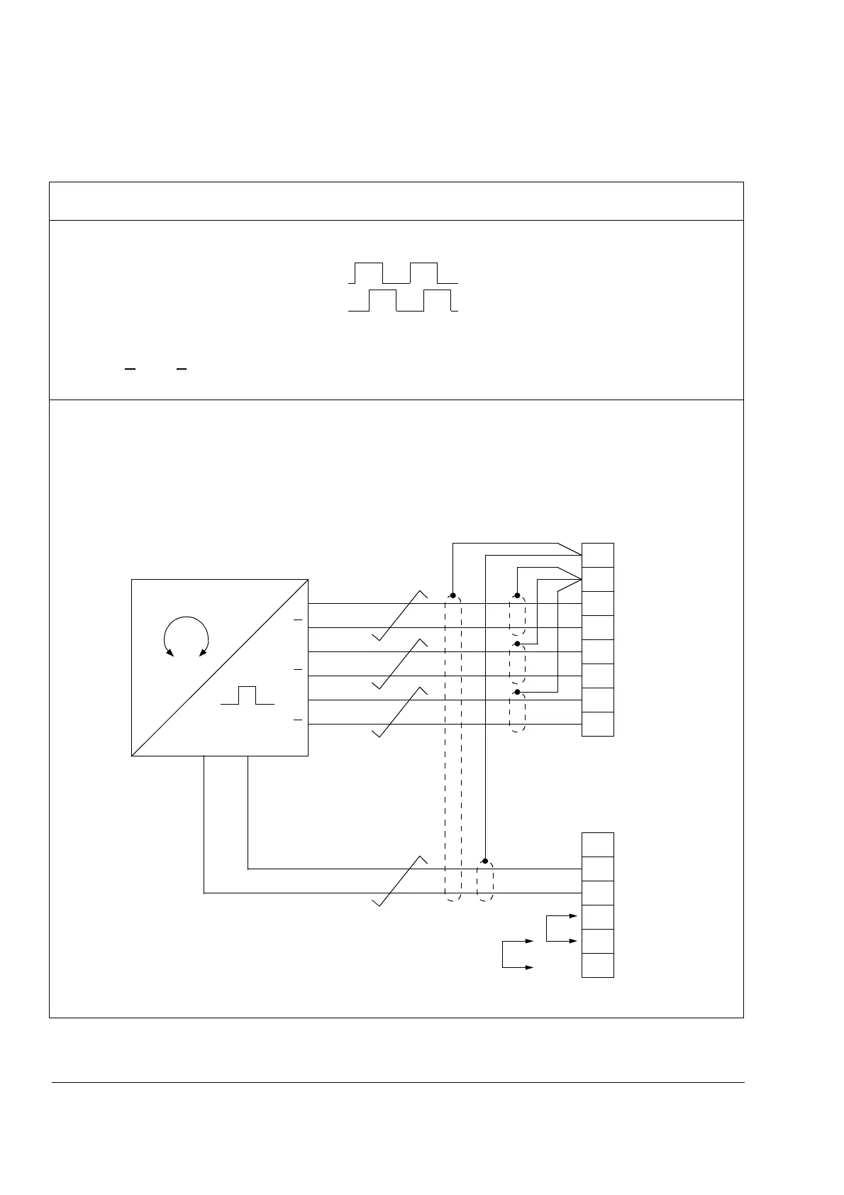
Wiring diagrams
Encoder output type: Push-pull
Output pulse order in Forward rotation: 1, 2
(With encoders with 2 as the leading output,
1 and 2 should be wired to RTAC terminals B+ and A+ respectively.
1
and 2 should be wired to RTAC terminals B- and A- respectively.)
Differential connection
Figure 3-3 Differential wiring of pulse encoders with push-pull outputs
1
2
1
1
0
0VVCC
2
X1
RTAC
A+
A-
B+
B-
Z+
Z-
2
0
15V
24V
Encoder supply
voltage selection
(15 or 24 V)
1
2
3
4
5
6
SHLD
SHLD
7
8
V OUT
+15V
V IN
+24V
1
2
3
4
5
6
0 V
0 V
X2