8 CI/SM500F–EN Rev. A
Cable entries
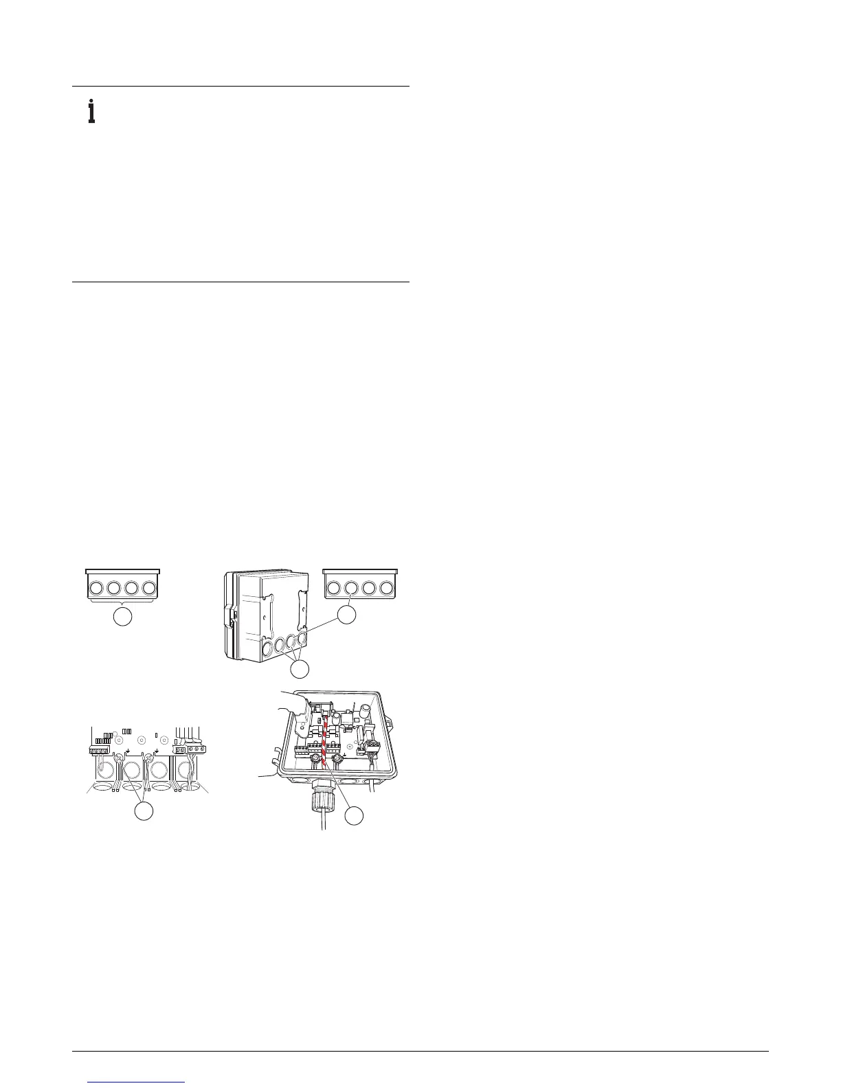
Referring to Fig. 6:
1. Route cables through four holes A provided on the
bottom of the case.
2. Knockouts B are provided on the rear of the recorder
case as an alternative means of cable entry. To remove a
knockout, place the back of the recorder on a firm, flat
surface, open the door and inner cover and carefully
remove the knockout by placing the blade of a small,
flat-bladed screwdriver into the knockout groove and
tapping the screwdriver smartly with a hammer.
3. Use cable entry hole or knockout C if the optional
Ethernet module is fitted.
4. Connect Ethernet cable D, ensuring that if optional input
modules are fitted in positions B and C, the cable is routed
between their terminal blocks as shown.
5. Connect cable screens only to terminals E.
IMPORTANT (NOTE)
– For wall- or pipe-mounting to IP66/NEMA4X
standard, fit suitable cable glands. Blank off any
unused holes with the blanking plugs and retaining
clips supplied with the recorder.
– Optional cable glands are available and are suitable
for use with cables Ø 5 to 9 mm (0.20 to 0.35 in.).
The alternative 2-hole cable gland inserts are
suitable for use with cables Ø 5 mm (0.20 in.). The
Ethernet cable gland is suitable for use with cable
Ø 4.8 to 6.3 mm (0.19 to 0.25 in.).
Fig. 6 Cable knockouts, ethernet cable routing
and cable screening connections

 Loading...


