S
Steven YoungSep 13, 2025
What causes vibration in ABB Industrial Equipment?
- RRichard SandovalSep 13, 2025
Vibration in ABB Industrial Equipment may be caused by rotor unbalance. In this case you should contact ABB Turbocharging Service Station.
What causes vibration in ABB Industrial Equipment?
Vibration in ABB Industrial Equipment may be caused by rotor unbalance. In this case you should contact ABB Turbocharging Service Station.
Manual's purpose is to familiarize user with turbocharger, its safe and efficient operation.
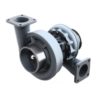
Details the internal and external components of the turbocharger and their roles.
Specifies turbocharger's design for diesel engines to generate air volume and charge pressure.
Covers storage for up to 6 months and long-term storage with VCI.
Covers organizational measures, safety checks, and modification approvals.
Explains symbols, notes, mandatory signs, and terms used in the manual.
Details the information on the rating plate: operating limits, intervals, and specifications.
Explains the meaning of values like nMmax, tMmax, and the impact of non-observance.
Details the locations where rating plates are attached to the turbocharger.
Provides contact details for ABB Turbocharging service stations and website.
Discusses residual risks during operation and maintenance, and personnel responsibilities.
States that ABB turbochargers fulfill Directive 2006/42/EC on machinery.
Illustrates and defines required personal protective equipment (PPE).
Explains the meaning of WARNING and CAUTION symbols and terms.
Describes the warning plates attached to the turbocharger that must be observed.
Provides instructions for safe operation, work area safety, and welding near the turbocharger.
Identifies mechanical hazards, noise risks, and hot surfaces.
Covers legal regulations and responsibilities for safe operation of pressure vessels.
Provides warnings and instructions for safely lifting turbocharger components.
Details requirements for the oil supply system, filtration, pressure, and temperature.
Outlines preventive visual controls and monitoring before and during commissioning.
Provides steps for recommissioning the turbocharger after a period of inactivity.
Addresses noise levels, hazards, and measures for noise reduction.
Outlines service intervals, inspections, and general servicing procedures.
Discusses recommended replacement intervals for rotating and non-rotating parts.
Describes the system for continuous monitoring of turbocharger speed.
Instructs to allow the engine to idle for 10 minutes before stopping for heat dissipation.
Explains the importance of visual checks and safety precautions during maintenance.
Details the procedure for removing, cleaning, and fitting the filter silencer components.
Explains wet cleaning procedures for compressor contamination.
Explains contamination sources and the importance of cleaning turbine components.
Covers procedures for mechanical cleaning of turbocharger components.
Lists causes and eliminations for sluggish start-up, vibrations, and rubbing parts.
Covers causes and eliminations for turbocharger surging and its effects.
Addresses issues like low oil pressure, reduced speed, and increased speed.
Addresses noises during run-down and short run-down times.
Troubleshoots issues with signal amplitude, sensor tip, and speed readings.
Provides weight specifications for TPL65 and TPL69 models.
Details steps for disconnecting lines, unplugging sensors, and lifting the turbocharger.
Covers procedures for fitting the turbocharger, checking oil orifices, and connecting lines.
Emphasizes trained specialists for cartridge group work and checking assembly devices.
Provides weights for individual turbocharger assemblies and complete compressor casing.
Details steps for removing and installing the air suction branch and filter silencer.
Explains how to measure axial clearance before and after fitting the cartridge group.
Details steps for removing the cartridge group, including disconnection and casing removal.
Details procedures for removing and installing the turbine diffuser and nozzle ring.
Provides steps for installing the cartridge group, including securing and tightening.
Describes procedures for removing and installing the nozzle ring at the turbine end.
Provides a table of tightening torques for various components and positions.
Lists options like locking rotor, fitting cover plate, and blocking inlets/outlets.
Details procedures and cautions for locking the turbocharger rotor.
Provides dimensions and instructions for manufacturing and fitting a cover plate.
Instructs to shut off casing outlet, gas inlet, and gas outlet with cover plates.
Explains fitting a bypass around the turbocharger for engines with one turbocharger.
Details mothballing measures based on engine lubricating oil condition.
Describes options for long-term storage, including component removal and sealing openings.
Lists data needed for inquiries and ordering, and how to order.
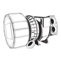
Provides an exploded view of the turbocharger with numbered parts and their designations.
Shows an exploded view of the turbine cleaning system with part numbers.
Illustrates the TPL65-A cartridge group with numbered parts and their designations.
Illustrates the TPL69-A cartridge group with numbered parts and their designations.
| Power | Not available |
|---|---|
| Max Pressure | Not available |
| Free Air Delivery | Not available |
| Noise Level | Not available |
| Weight | Not available |
| Dimensions | Not available |