TPU2000/2000R Modbus/Modbus Plus/ Modbus TCP/IP Automation Guide
104
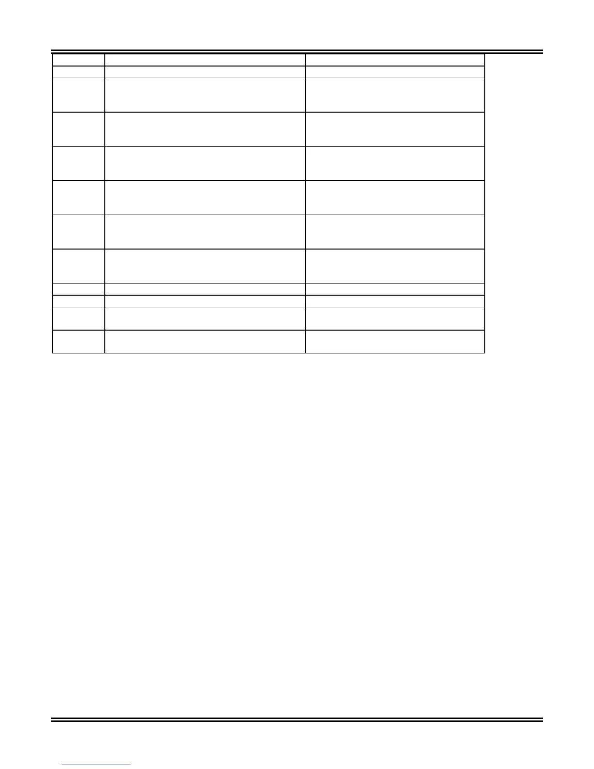
0<=Range<= 9999
41029 Through Fault Counter Unsigned Integer 16 Bits
41030 Through Fault KSIA
Kiloamps Symmetrical Ia – Current existing
when breaker opened on Phase A.
Signed 32 Bit High Order Word MSW
41031 Through Fault KSIA
Kiloamps Symmetrical Ia – Current existing
when breaker opened on Phase A.
Signed 32 Bit Low Order Word LSW
41032 Through Fault KSIB
Kiloamps Symmetrical Ib – Current existing
when breaker opened on Phase B.
Signed 32 Bit High Order Word MSW
41033 Through Fault KSIB
Kiloamps Symmetrical Ib – Current existing
when breaker opened on Phase B.
Signed 32 Bit Low Order Word LSW
41034 Through Fault KSIC
Kiloamps Symmetrical Ic – Current existing
when breaker opened on Phase C
Signed 32 Bit High Order Word MSW
41035 Through Fault KSIC
Kiloamps Symmetrical Ic – Current existing
when breaker opened on Phase C
Signed 32 Bit Low Order Word LSW
41036 Through Fault Cycle Summation Counter Signed 32 Bit High Order Word MSW
41037 Through Fault Cycle Summation Counter Signed 32 Bit Low Order Word LSW
41038 Overcurrent Trip Counter Unsigned 16 Bit
0 – 9999
41039 Differential Trip Counter Unsigned 16 Bit
0 – 9999
Discrete 4X Register Bit Data Reporting (26 Registers Defined)
The TPU2000 and TPU2000R offers bit status reporting via 0X and 1X Modbus/Modbus Plus command retrieval.
Some hosts however do not offer the capability to read data via these data types. The data types have been
structured to be reported in 4X data types. Reported data is of the following types:
Logical Outputs
Logical Inputs
Physical Inputs
Forced Physical Input State Reporting
Forced Physical Output State Reporting
Forced Logical Input State Reporting
The following registers only report the status of the elements. Some of the elements are latched and behave as
do their 0X and 1X counterparts. The bits are reset depending upon the reset control via the 4X control registers
(Reference Section 5).
It should be noted that for the following bits, the operational characteristics are included for reference:
TCFA – Trip Circuit Failure Alarm – This bit indicates that the Trip Circuit is Open. The Alarm remains
continuously energized (value = 1) until circuit continuity is sensed.
TFA – Trip Failure Alarm – This bit indicates that a fault has not been cleared within the programmable Trip
Failure Time setting of 5 to 60 Cycles. Use the Trip Failure Mode Setting (Differential, Overcurrent, or Differential
and Overcurrent) to select the type of faults for which a trip failure alarm will be given. The Trip Failure Alarm
clears when the current drops below the Trip Failure Drop-Off setting.
PUA - Pick Up Alarm: Differential and Overcurrent (87/51/50/150/46) Pickup Alarm. Indicates that an enabled
protective function is picked up and can be used as a fault detector alarm. The Alarm Resets 500 mS after the
“picked up” state has dropped out.