10 TTF200 FIELD-MOUNT TEMPERATURE TRANSMITTER | OI/TTF200-EN REV. B
… 2 Use in potentially explosive atmospheres in accordance with
ATEX and IECEx
… Electrical connections
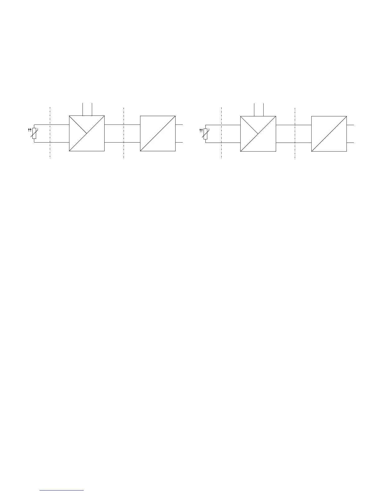
ATEX - Zone 1 (0)
Marking: II 2 (1) G Ex [ia IIC Ga] ib IIC T6 Gb
Zone 0 or 1 Ex area Zone 1 Safe area
A10127
ib
ia
J
ia
D
A
CB
A Sensor
B TTF200 transmitter
C Supply isolator [Ex ib]
D Interface for LCD indicator
Figure 5: Hookup in ATEX - Zone 1 (0)
The input for the supply isolator must be designed with ‘Ex ib’
type of protection.
As the user, it is your responsibility to ensure that the sensor
instrumentation meets the requirements of applicable explosion
protection standards.
The sensor can be installed in Zone 1 or Zone 0.
When using the transmitter in Zone 1, you must ensure that
impermissible electrostatic charging of the temperature
transmitter is prevented (observe the warnings on the device).
ATEX - Zone 1 (20)
Marking: II 2 G (1D) Ex [ia IIIC Da] ib IIC T6 Gb
Zone 20 or 21 Ex area Zone 1 Safe area
A10128
ib
ib
J
D
ia
ia
CB
A
A Sensor
B TTF200 transmitter
C Supply isolator [Ex ib]
D Interface for LCD indicator
Figure 6: Hookup in ATEX - Zone 1 (20)
The input for the supply isolator must be designed with ‘Ex ib’
type of protection.
As the user, it is your responsibility to ensure that the sensor
instrumentation meets the requirements of applicable explosion
protection standards.
The sensor can be installed in Zone 20 or Zone 21.
When using the transmitter in Zone 1, make sure that
impermissible electrostatic charging of the temperature
transmitter is avoided (observe the warnings on the device).