Do you have a question about the ABB Unitrol 1000-PM40 and is the answer not in the manual?
Instructions for installation, commissioning, operation, and maintenance of the excitation system.
Explanation of safety symbols (DANGER, WARNING, CAUTION, NOTICE, IMPORTANT) and their implications.
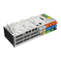
Introduces the UNITROL 1000-PM40 power module, its technology, and physical structure.
Specifies the module's use for excitation of indirectly excited synchronous machines with UNITROL 1000-15.
Describes the physical assembly including heat sink, sidewalls, cover, and terminals.
Details site requirements (dry, dust-free) and mounting methods (wall/rack, cooling clearance).
Provides step-by-step instructions for safely removing the unit's cover.
Illustrates the physical and electrical connection between UNITROL 1000-15 AVR and the Power Module.
Shows electrical connections for digital/analog I/O, power supply, and control signals.
Details the power module's components: rectifier, soft start, IGBT, and over-voltage protection.
Explains control and monitoring via CAN Bus communication between UNITROL 1000-15 and the module.
Notes the potential-free relay contact for alarms and refers to LED display section.
Details connections for auxiliary supply (L1, L2, L3) and excitation current output (+le, -le).
Describes connections for alarm relay contact (COM, NO, NC) and CAN Bus signals.
Specifies the earth connection point for safety grounding.
Internal shutdown for 100ms CAN communication interruption during excitation ON.
Heat sink temperature alarms/shutdowns and excitation current overcurrent alarms.
Shutdown triggered by inrush current limiter (ICL) if unit cannot restart.
Explanation of Power ON, Excitation ON, Overcurrent, Overtemperature, and Alarm LEDs.
Relay indicates alarm when powered; off during normal operation or when unpowered.
Illustrates the sequence of LED indications during the unit's startup process.
Details mounting: four screws, indoor, dry, dust-free, no gases/acid fumes.
Specifies cable cross-sections for terminals and recommended wiring practices.
Recommends qualified personnel, metallic casing recycling, and hazardous element separation.
Warns of high voltages (up to 250 VAC) and requires shutdown/grounding before commissioning.
Directs to UNITROL 1000-15 manual for settings; no configuration on power module.
Reiterates electric shock danger and requires shutdown/grounding for maintenance.
Recommends checking terminal tightness and cleaning cooling flanges.
Suggests checking LED displays (section 2.3.5) to diagnose faults.
Advises sending defective units for repair, referring to manufacturer's details on page 2.
Provides specifications: designation, weight, dimensions, climatic, electrical data, and CE conformity.
| Brand | ABB |
|---|---|
| Model | Unitrol 1000-PM40 |
| Category | Control Unit |
| Language | English |