Document number Lang. Rev. ind. Page
ABB Switzerland Ltd
3BHS200200 E80
en A 9
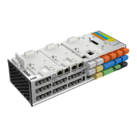
2.3.1 Interface to the Power Module
Structure of automatic voltage regulator and power module:
Automatic Voltage Regulator
UNITROL 1000-15
Power Module 40 A Miniature Circuit-
Breaker
UNITROL 1000
Ab b
R
UNITROL 1000
Power Module 40 A
Ab b
Power ON
Excitation ON
Overcurrent
Overtemperature
Alarm
CAN ALARM Ie Upwr
+-
L3L1 L2
OK
ESC
CAN BUS
S283- UC-Z
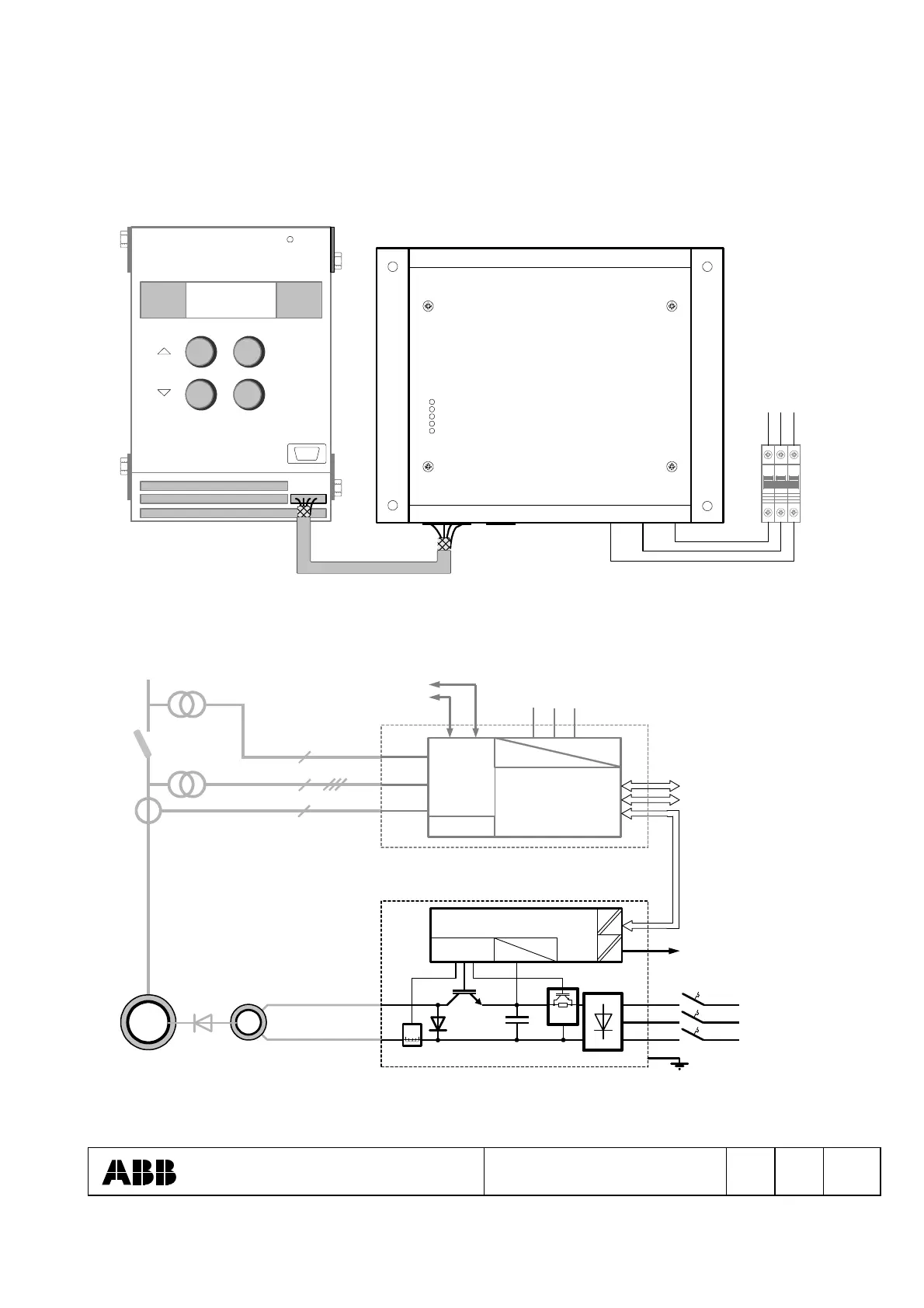
Connection diagram machine, voltage regulator UNITROL 1000-15 and Power module:
PWM
-
+
Measurement
and control
inputs
~ / =
=
Auxiliary supply UAUX
L1 L2 L3
(+) (-)
AVR
Supply
power electronics
L1
L2
L3
Digital in- and outputs
Analog in- and outputs
UNET
UM
IM2
Ie
UN1000-15
E
SM
E
for control electronics
RS-232
RS-485
Power Module 40 A
CAN Bus
=
=
ALARMPWM
or
U
pwr
 Loading...