Document number Lang. Rev. ind. Page
ABB Switzerland Ltd
3BHS200200 E80
en A 8
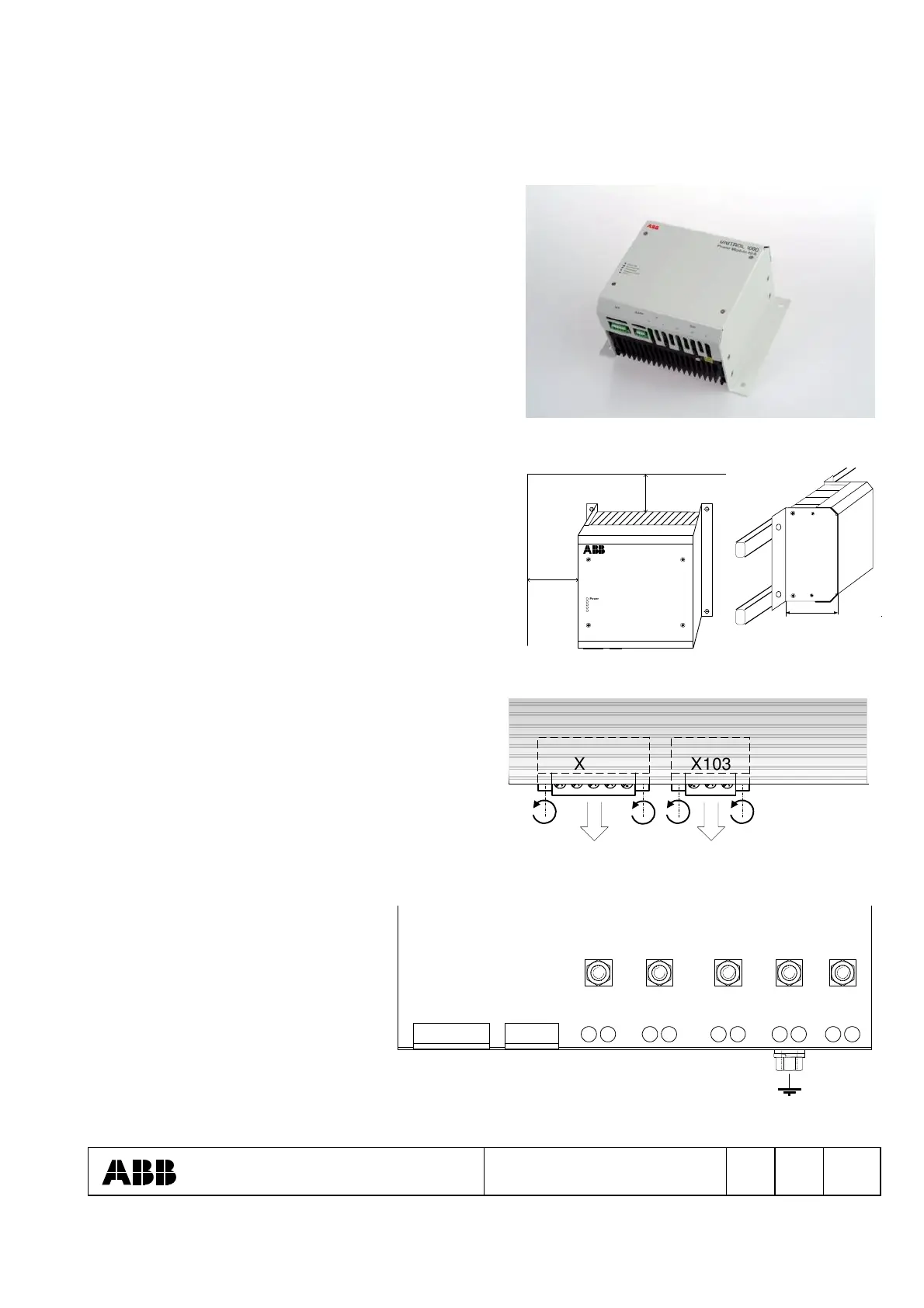
2.3 Hardware
Structure:
A solid heat sink with two sidewalls and a cover made
of metal form the equipment assembly.
The semiconductors are mounted on the heat sink and
electrically connected with the printed circuit board,
which is fastened on top of it.
The terminals are at the front side of the unit.
Installation:
The site of installation must be dry and free of dust.
Mounting:
Power module is designed for wall or rack mounting.
For optimal cooling a distance of approx. 200 mm
around the unit must be kept free.
Wall mounting
UNITROL 1000
Power Module 40 A
Power ON
Excitation ON
Overcurrent
Overtemperature
Alarm
CAN ALARM Ie Upwr
+-
L3L1 L2
200 mm
200 mm
Rack mounting
154 mm
Dismantling the cover:
Both system plugs X102 and X103 are to unbolt
and to remove.
Subsequently, unbolt the four screws on the cover.
Now the cover can be raised and removed from the
side of the connector.
open screws
remove connectors
CAN ALARM
X103X102
Cover
Connectors: Cover removed
- Phoenix system plugs X102, X103
(CAN, ALARM)
- Screw connections M5 on printed
circuit board (Ie, Upwr)
- Screw connection M5 on front of
heat sink (Earth)
L1 L2 L3
+Ie
-Ie
X103X102
1 1
Upwr
ALARMCAN
Printed circuit board mounted on the heat sink
 Loading...