Document number Lang. Rev. ind. Page
ABB Switzerland Ltd
3BHS200200 E80
en A 14
3 INSTALLATION AND DISPOSAL
The unit should be unpacked with the usual degree of care, without use of force and using suitable tools.
The unit should be inspected visually to check for any damage caused during transport. Complaints
regarding defects resulting from inappropriate transport are to be addressed immediately to the receiving
station or the last carrier.
NOTICE!
The unit is visible damaged.
The safe operation is not possible.
The unit must not be installed and taken in operation
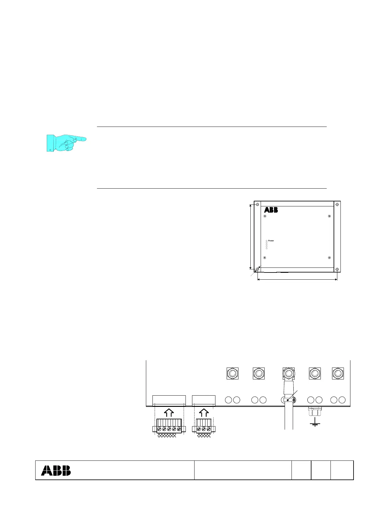
3.1 Mechanical installation
The unit is mounted in place by means of four screws.
See dimensional diagram for fixing holes and spacing.
The unit should only be installed in indoor areas which are dry
and dust-free and which do not contain any gases, acid fumes
or similar.
UNITROL 1000
Power Module 40 A
Power ON
Excitation ON
Overcurrent
Overtemperature
Alarm
CAN ALARM Ie Upwr
+-
L3L1 L2
180 mm
256 mm
3.2 Earthing and wiring
Cross sections of the terminals:
- L1...L3, +Ie and –Ie: Screw terminal power circuits, max. 16 mm
2
, (AWG 5)
- CAN BUS: Shielded signal cable, 2x 2x 0,34 mm
2
, Impedance 120 Ohm
- ALARM: Signal cable, max. 2,5 mm
2
, (AWG 13)
- Earth: at least 6 mm
2
(AWG 9), however not smaller than wiring of power circuits
The cables of the power circuits
are recommended to wire with
shielded cables.
The screw terminals and the
grounding connection are to be
tightened with a torque of 3 to
5 Nm
L1 L2 L3
+Ie
-Ie
X103X102
1 1
Upwr
after assembly of the cover
cable tie
 Loading...