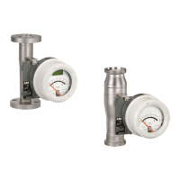
20 VA Master FAM540 METAL CONE VARIABLE AREA FLOWMETER | OI/FAM540-EN REV. E
Change from two to one column
… 2 Use in potentially explosive atmospheres in accordance with ATEX and IECEx
… Operating instructions
Changing the type of protection
Depending on the model, the device may be designed to be installed in one of the applications listed. If you plan to use a device that
was installed in one type of protection rating in a different type of protection rating, some measures must be taken before
connecting voltage to the device.
Measures for devices with alarm signaling unit FAM540-B/C/D
Original installation New installation Necessary test steps
XP or Ex d
U
M
= 60 V
IS or Ex ia* • 500 V AC / 1min test between terminals 51 / 52 and 41 / 42 and terminals 51 / 52 / 41 / 42 and
the housing.
• Visual inspection: no explosion, no damage.
NI or Ex ec • 500 V AC / 1min test between terminals 51 / 52 and 41 / 42 and terminals 51 / 52 / 41 / 42 and
the housing.
• Visual inspection: no explosion, no damage.
IS or Ex ia XP or Ex d • Visual inspection: no damage to threads (cover, surface, ½” NPT cable input), cable gland,
glass, housing, locking device for cover, suited cable, etc.
NI or Ex ec
No special measures required.
NI or Ex ec
U
M
= 60 V
IS or Ex ia* • 500 V AC / 1min test between terminals 51 / 52 and 41 / 42 and terminals 51 / 52 / 41 / 42 and
the housing.
• Visual inspection: no explosion, no damage.
XP or Ex d • Visual inspection: no damage to threads (cover, surface, ½” NPT cable input), cable gland,
glass, housing, locking device for cover, suited cable, etc.
* Possible only if the maximum signal levels of U
M
≤ 60 V (e.g., PELV or SELV circuits) were not previously up-scaled.
Measures for devices with transmitter with or without LCD display FAM540-E/F
Original installation New installation Necessary test steps
XP or Ex d
U
M
= 60 V
IS or Ex ia*
• 500 V AC / 1min test between terminals 31 / 32 and 41 / 42 and terminals 31 / 32 / 41 / 42 and
the housing.
• Visual inspection: No damage, especially to electronic boards.
• Visual inspection: no explosion, no damage.
NI or Ex ec
• 500 V AC / 1min test between terminals 31 / 32 and 41 / 42 and terminals 31 / 32 / 41 / 42 and
the housing.
• Visual inspection: No damage, especially to electronic boards.
• Visual inspection: no explosion, no damage.
IS or Ex ia XP or Ex d
• Visual inspection: no damage to threads (cover, surface, ½” NPT cable input), cable gland,
glass, housing, locking device for cover, suited cable, etc.
NI or Ex ec
No special measures required.
NI or Ex ec
U
M
= 60 V
IS or Ex ia*
• 500 V AC / 1min test between terminals 31 / 32 and 41 / 42 and terminals 31 / 32 / 41 / 42 and
the housing.
• Visual inspection: No damage, especially to electronic boards.
XP or Ex d
• Visual inspection: no damage to threads (cover, surface, ½” NPT cable input), cable gland,
glass, housing, locking device for cover, suited cable, etc.
* Possible only if the maximum signal levels of U
M
≤ 60 V (e.g., PELV or SELV circuits) were not previously up-scaled.
Change from one to tw o columns

 Loading...