24 | Manual ZX0 HB 600 en - Revision 05
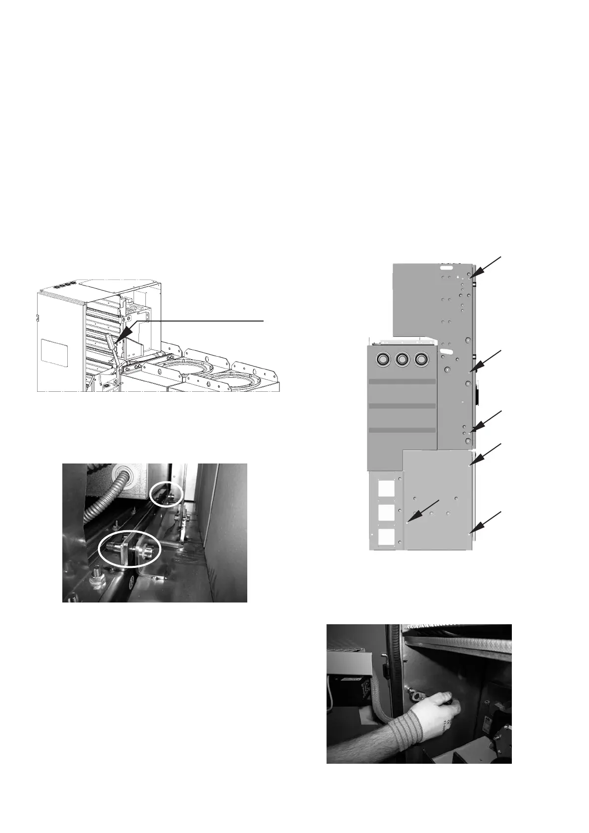
Fig. 2.3.2.6: Screw connections between the panel blocks: Accessibility of
the front screw connection from the inside of the low voltage compart-
ment
Tool inside
the low voltage compartment
− Slide the extension panel carefully against the existing sys-
tem without tipping it, in such a way that the contact tubes
slide into the busbar sockets and the guide pins into the
corresponding bores in the fastening bracket.
?
Apply drawing or pressing tools to a large area on
the panel blocks directly above the floor (for
instance by using a wooden beam between the tool and the
panel block) so as to avoid damage to the panel block.
− As soon as the distance between the two panel blocks is
small enough, insert two M10 x 40 cheese head screws
into the bores provided in the fastening bracket. Disman-
tling the lid in the rear wall of the low voltage compartment
Fig. 2.3.2.7: Complete screw connections on the fastening brackets
Fig. 2.3.2.8: Further fastening points on the panel blocks
Fig. 2.3.2.9: Screwing the low voltage compartments together
facilitates access to the front screw connection from inside
the low voltage compartment (figure 2.3.2.6).
− The rear screw connection is located behind the low volt-
age compartment. Turn both the screws into the pulling
nuts on the previously assembled threaded plate and
tighten the screws alternately (figure 2.3.2.7 ).
− Connect the low voltage compartments and cable termina-
tion compartments of the two panel blocks at the specified
locations (figure 2.3.2.8) with the aid of screws.