Do you have a question about the Absen A27 Plus Series and is the answer not in the manual?
Precautions to prevent electric shock during installation and operation.
Safety measures to prevent fire hazards, including ventilation and temperature limits.
Safety guidelines to avoid injury during installation, handling, and operation.
Information on recycling and proper disposal of product components.
Details on the A27 Plus series' key features and optional versions.
Detailed technical specifications for various A27 Plus models, including pixel pitch and dimensions.
Diagram illustrating the physical dimensions of the A27 Plus cabinet.
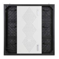
Diagram illustrating the physical dimensions of the A27 Plus module.
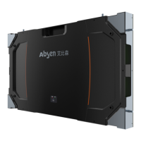
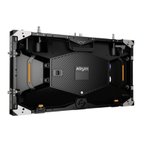
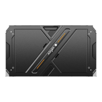
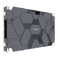
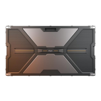
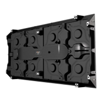
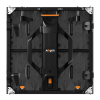
Overview of the cabinet structure, including handles and locking screws.
Illustrations of mounting frames for wall installation (single and double).
Information on single and double hanging bars for installation.
Details on data jumper cables for vertical and horizontal connections.
Details on power jumper cables for vertical and horizontal connections.
Information on the 10m power cable for video wall power input.
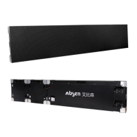
Description of standard packaging, dimensions, and weight for modules and cabinets.
Details on connector plates and M8x60 screw bolts for steel structure installations.
Instructions for mounting cabinets onto walls or steel structures using front mounting holes.
Steps for installing the mounting frame onto a flat wall using M6 screws or anchors.
Procedure for rear installation, involving connecting screws and plates.
Guidelines for rigging installation, including fixing hanging bars and connecting blocks.
Steps to check power and data cables before applying power and signal.
Detailed instructions for connecting power supply cables to cabinets.
Details on using RJ45 CAT5 network cables for signal connection.
Instructions for connecting signal cables using HDMI for the smart version.
Procedure to test for short circuits in AC input and DC output before powering on.
List of tools required for performing maintenance on the product.
Instructions for performing maintenance tasks on the product.
Procedure for removing and replacing modules using the front service tool.
Steps to remove and maintain the HUB board using a Phillips screwdriver.
Procedure for replacing the receiving card, requiring HUB board removal first.
Steps to remove and maintain the power supply unit from the back of the HUB board.