Do you have a question about the Absen PL V2 Series and is the answer not in the manual?
To prevent electric shock, ensure proper grounding, disconnect power during lightning, and turn off the master switch before maintenance.
Use circuit breakers, maintain ventilation, avoid obstructing the screen, do not modify, and do not exceed 55°C ambient temperature.
Wear helmets, ensure structures withstand equipment weight, secure stacked products, and avoid looking directly at the screen without protection.
Information on recycling components and contacting local authorities for disposal information.
Highlights features like curve version, high brightness, HDR10, 16bit grayscale, 3840Hz refresh rate, and advanced locking system.
Detailed specifications for PL V2 indoor models, including LED type, pixel pitch, cabinet dimensions, refresh rate, and power consumption.
Detailed specifications for PL V2 outdoor models, including LED type, pixel pitch, cabinet dimensions, refresh rate, and power consumption.
Visual representations of cabinet dimensions in millimeters, showing front, side, and depth views.
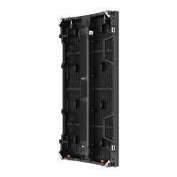
Identifies and illustrates key internal components of the LED cabinet, such as magnetic locks, locking systems, modules, and power boxes.
Details on using hanging bars for rigging installation, including illustrations and step-by-step instructions for connecting cabinets.
Guidelines for stacking LED cabinets, noting the support for radian connection from -7.5° to +10°.
Essential precautions for installing PL V2 series as floor tile screens, including screw placement for stability.
Pre-cabling checks for power/signal circuits, voltage requirements, and power consumption calculations for safe operation.
Information on connecting power and signal cables using aviation connectors, and basic wiring operation steps.
Illustrates a typical wiring setup for connecting the screen system to a video source and distribution box.
Lists and illustrates essential tools required for LED screen maintenance, such as screwdrivers, multimeters, and levels.
General guidance for performing maintenance, with specific steps for module front and rear maintenance procedures.
Detailed steps for front and rear module maintenance, including using specialized tools for removal and replacement.
Step-by-step instructions for the maintenance and replacement of power boxes in 500x500mm and 500x1000mm cabinets.
Introduces maintenance procedures for critical electronic components like receiving and HUB cards, showing component examples.
Guides on performing rear maintenance for receiving cards, including screw removal and proper reinstallation with directionality.
Instructions for rear maintenance of the HUB board, referencing receiving card procedures and secure screw fixing.
Steps for front maintenance of receiving cards, involving cabinet disassembly to access and replace the card.
Specific steps for removing and replacing the power supply unit, requiring a Phillips screwdriver for screw removal.
Details on PL V2 series flight cases, highlighting their design for transport, stackability, and available configurations.
Steps to diagnose and resolve issues when specific modules on the screen appear black, checking power and data connections.
Solutions for a completely black screen, covering power status, cable connections, sending card, and video card drivers.
Steps to fix scrambled images, focusing on receiving card seating, data cables, firmware, and computer issues.
Addresses color differences between modules, suggesting checks for module seating, data cables, and sending card indicators.
Guides on ensuring all panels display the same content by checking software settings and data port connections.
Steps to resolve the issue of no control system detection, checking USB cables, ports, and drivers.
Solutions for when the multi-function card is not detected, checking its power, data cable, and card seating.
Steps to resolve issues where the screen shows no full display, checking playback window and video processor output.
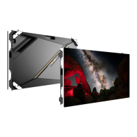
The Absen PL V2 Series is a display product specifically engineered for stage rental applications, making it ideal for large-scale events such as concerts, shows, auto shows, and business activities where high-quality video broadcast and information release are crucial. This series offers a comprehensive range of pixel pitches, including indoor versions (PL1.9 V2, PL2.5 XR V2, PL2.5 Pro V2, PL2.5 Plus V2, PL2.9 V2, PL3.9 V2, PL2.9 Plus V2, PL3.9 Plus V2) and outdoor versions (PL2.9 Pro V2, PL3.9 Pro V2, PL3.9W Plus V2, PL4.8 Pro V2, PL4.8W Plus V2). The product line also includes curve versions (PL2.5 Pro & PL2.9), providing enhanced flexibility for creative stage designs.
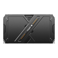
The PL V2 series cabinets are constructed from die-casting aluminum, ensuring excellent flatness, high-quality finish for both the cabinet and modules, and superior structural strength. This robust design contributes to the display's reliability and aesthetic appeal in demanding rental environments.
The PL V2 series display is designed for versatile installation, supporting both rigging and stacking configurations. A key feature is its advanced locking system with a safety mechanism, which facilitates one-person installation, significantly streamlining setup times for events. The curved lock mechanism allows for radian connections ranging from -7.5° convex to +10° concave, offering unlimited flexibility in design and enabling the creation of dynamic and immersive visual experiences.
For hanging installations, the system utilizes single or double hanging bars, and even a 90-degree hanging bar for specific configurations. These hanging bars are capable of supporting a substantial number of panels: up to 20 500x500mm panels or 10 500x1000mm panels. The installation process involves fixing the hanging bar to a truss, aligning the cabinet's safe lock with the mounting hole on the beam, pressing the locking plate, inserting the safe lock, and then tightening the safe lock from left to right, followed by the second cabinet. Detailed installation steps are also available via product installation videos.
Stacking installations are also supported, with cabinets equipped with curved locks to achieve radian connections from -7.5° to +10°. For floor tile screen applications, specific precautions are necessary. Two M3 fixing screws must be installed on the lower side of the power supply box to prevent it from loosening or falling. This is particularly important for PL3.9W Plus V2 (500x500mm cabinet), PL3.9 Pro V2 (500x500mm cabinet), PL4.8W Plus V2 (500x500mm cabinet), and PL4.8 Pro V2 (500x500mm cabinet) models when used as floor tiles. Each panel requires two screws on the power box. After installing the box and connecting the wires, 12 M1.6*12mm screws are used to install an acrylic board on each box. It is crucial to implement a constraint coverage structure around the entire screen to prevent displacement of the PC mask during strong vibrations. The floor tile screens boast a load capacity of 2000KG/SQM.
Before cabling, users must carefully verify the power and signal circuit connections to prevent short circuits between the L, N, and PE lines of each cabinet's AC power input using a multimeter. Power connection instructions emphasize calculating and selecting the appropriate distribution box or socket based on maximum power consumption. The input voltage for cabinets is 100-240V/AC, utilizing 3X2.5mm/sqm power cables between the distribution box and the cabinet. The number of cabinets loaded per power cable varies depending on voltage and product models. Network and power cables for all series are connected via aviation connectors. It is recommended that connecting cables pass through the cabinets as much as possible. After wiring, a multimeter should be used to check for short circuits between the AC input (L/N/PE) and DC output (VCC/GND) of the power supply.
The display supports high-definition content playback, including video, text, and images. It is advised to match the content resolution with the screen's resolution to avoid compression and maintain optimal performance. Software operations are detailed in a separate instruction manual. The number of cabinets that wires can carry varies based on cabinet size and input voltage, with specific tables provided for AC220V and AC110V environments. The resolution should be calculated based on each box pixel, and the signal line connected according to the sending card's load range, with a maximum of 655360 pixels per network port.
The PL V2 series is designed for ease of maintenance, featuring a modular design that supports fast maintenance of modules and power boxes. All cabinets can be customized to support both HUB and PCB front maintenance.
Tools for Maintenance:
Module Maintenance: The modules of the PL V2 series support both front and rear maintenance.
Module Front Maintenance:
Module Rear Maintenance:
Power Box Maintenance:
500x500mm Cabinet:
500x1000mm Cabinet:
Receiving Card, HUB Card, and Power Maintenance: All series products support rear maintenance for the receiving card and HUB board. Additionally, all products' receiving cards and HUB boards can be customized for front maintenance.
Receiving Card Rear Maintenance:
HUB Board Rear Maintenance: Refer to the receiving card maintenance method. Remove the fixing screw (marked with a red circle) during maintenance.
Receiving Card Front Maintenance:
Power Maintenance:
Flight Case: Flight cases are designed to protect LED panels from SMD damage during transport and are optimized for low-cost vehicle transport. They are fully stackable to save space.
Troubleshooting Common Faults: The manual provides a comprehensive troubleshooting guide for common issues, including:
Power Supply Short Circuit Check: After completing cabinet wiring, use a multimeter to check for any short circuit at the AC input power supply (L/N/PE) and DC output terminal (VCC/GND). If a short circuit is detected, thoroughly investigate the wiring to ensure all connections are correct before powering on the unit.
| Refresh Rate | 3840 Hz |
|---|---|
| Contrast Ratio | 5000:1 |
| Lifespan | 100, 000 hours |
| Pixel Pitch | 2.5mm |
| Brightness | 1000 nits |
| Operating Temperature | -20°C to 50°C |
| Cabinet Size | 500mm x 500mm |
| IP Rating | IP65 |