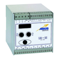
Page 4 Data : 01.03.2016
In order to prevent a load from being lifted in inching
operation, an inching counter is integrated in the sy-
stem. This counter shuts down the hoist motor if the s et
limit is exceeded without load evaluation being possi-
ble.
If the preset load limits are exceeded, hoist movement
is stopped or other appropriate action is initiated using
relay contacts.
2.1 Overload Shut–Down
Overload shutdown thresholds can be s et between 0
and 110 % of rated load using the DBE operator termi-
nal. The values given in this section are based on the
standard setting of 110 %. The LIS–SE is equipped w ith
two relays for enabling the main and precision lifting
speed. If the overload threshold is exceeded, t hese re-
lays shut the hoist down. At the same time, the load in-
dicator display flashes at intervals of one second.
The unit implements two types of overload shut–down
function:
a) Static overload shut–down. Static loads must not
exceed 110 % of the rated value. The actual load va-
lue is averaged over the measurement time and
compared with the threshold. This prevents prema -
ture shut–down caused by dynamic load peaks. If
the static load measured exceeds 110 % of the ra-
ted value, the two output relays are shut down.
b) Shut–downonsuddenloadincrease.Iftheloadin-
creases too rapidly, the relay for the main lifting
speed is shut down. The relay is only re–activated
when the load has ceased to increase, provided
that the maximum load has not been exceeded.
This function prevents rope breakage as a result of
lifting an excessive load with a loose rope at main
lifting speed. Also, excessive force on the rope is
prevented if the crane hook is suddenly blocked.
Note:
In the event of an overload shut–down, the
load can always be lowered using the preci-
sion lifting speed. The ”overload” status is
only reset if the load is lowered for at least one
second.
The overload s tatus is not reset by a power
failure or by operation of the EMERGENCY
SHUT–DOWN switch.
2.2 Part–Load Switch
In some applications, another shut–down point below
the rated load is required in addition to the overload
shut–down. This may be the case if part of the hall
structure is not designed for the entire load capacity of
a crane system.
The LIS- SE allows the user to set an additional shut-
down point (which can be adjusted via parameter
4.0).As soon as a signal is available at input EA of the
unit, the lifting relays drop out when the value set in pa-
rameter 4. 0 is exceeded.
The unit is then s witched to the overload mode.
A current transformer module with an additional swit-
ching relay may be used for more complex applica-
tions. The switching point for this relay may be set to
any value between 0 and 110 % of rated load capacity
using parameter P 4.2.
2.3 Taring
The load indicated can be set to zero with a defined
load on the hook (for example, the weight of load
supports) using the tare button (TARA) which is
normally incorporated in the pendant control. To do so,
this button must be pressed for at least 3 sec. during
lifting until the display is reset to zero.
Before taring, a load must have been measured.
This procedure can be repeated at any time.
If a load lower than the value previously used for taring
is lifted, the value ”–0.00” is displayed, indicating that
the current load is lower than the tare load.
The tare value stored is deleted if the tare button is
pressed for about 3 sec. when the hoist is stationary.
2.4 Load Population Recorder
(optio nal)
If a load population recorder is integrated in the LIS–
SE, the actual operating conditions of a hoist can be re-
corded. I n addition to the total running time T, which is
equivalent to the time during which the motor is swit -
ched on, the actual load on the hoist is recorded. For
this purpose, the unit evaluates the load measure-
ments on a continuous basis.
The LIS–SE unit calculates the actual use S, the load
spectrum factor Km and the remaining service life of the
hoist in accordance with FEM 9.755 from these values.
The load spectrum factor is equivalent to the load po-
pulation with which the hoist was operated.
2.4.1 FEM Groups
The EU machinery directive calls for precautions to be
taken to prevent risks caused by fatigue and ageing on
hoists and cranes. The following precautions have the-
refore been taken in order to achieve safe working pe-
riods (S.W.P.).
Cranes and hoists are subdivided into various groups
in accordance with FEM 9.511.
The operator of a standard hoist is responsible for en -
suring that the a ctual operating conditions of the hoist
are recorded and documented in the test book at least
once per year. In the course of regular inspection, the
inspector must verify and determine whether the hoist
is still being operated within its safe working period.